Structures and thermal control (STR/TCS)
Also known as STR, TCS, Structure, Thermal control, Mechanisms
The frame that carries launch loads, the mechanisms that deploy antennas and arrays, and the thermal design that keeps every part within its temperature range. Small-satellite frames are mostly machined aluminium; thermal control relies on surface finishes.
- Document
- SQ-SS-005
- Updated
- Reading time
- 7 min
In this tab
Definition
The structure is the frame that carries every component, the interface surfaces that touch the deployer and the mechanisms of deployable elements such as antennas and arrays. Thermal control keeps every component within its allowed range while the heat loads change around the orbit. The two are designed together, because inside a spacecraft heat flows mostly through the structure.
Structure
The CubeSat Design Specification recommends aluminium alloy structures; 7075, 6061, 6082, 5005 and 5052 are typical for the main frame and rails. Aluminium surfaces in contact with the deployer rails must be hard anodized to prevent inside the deployer[1].
Most commercial CubeSat frames are machined from 6061 or 7075 aluminium, and 1U, 3U and 6U frames are the most common products; some CubeSats have flown with printed polymer structures instead of metal[2]. PocketQubes use aluminium frames too, but many 1P designs let their printed circuit boards carry the loads: SMOG-1 has no separate frame at all, only boards and threaded rods[3].
Thermal environment
A spacecraft in low Earth orbit sees three external heat sources: direct sunlight, about 1361 W/m²[4]; sunlight reflected by the Earth (albedo, about 0.3 on average); and the Earth’s infrared emission, about 237 W/m² on average[5]. Internal dissipation from electronics and battery adds to these. The only way back out is radiation to space.
flowchart LR
  SUN["Direct sunlight"] --> SAT["Spacecraft surfaces"]
  ALB["Albedo"] --> SAT
  IR["Earth infrared"] --> SAT
  INT["Internal heat: electronics, battery"] --> SAT
  SAT --> SPACE["Radiation to space"]
Passive and active control
Small-satellite thermal design is dominated by traditional passive technology: paints, coatings, tapes, multilayer insulation () and thermal straps. Active control is mostly limited to battery heaters governed by a thermostat or a temperature sensor[6].
Materials
| Material | Density (g/cm³) | E (GPa) | Yield (MPa) | Tensile (MPa) | α (ppm/K) | k (W/(m·K)) | SCC resistance (ECSS-Q-ST-70-36C) | PocketQube clause |
|---|---|---|---|---|---|---|---|---|
| Al 6061-T6 | 2.70 | 68.9 | 276 | 310 | 23.6 | 167 | High resistance | Mat-02 |
| Al 7075-T6 | 2.81 | 71.7 | 503 | 572 | 23.4 | 130 | Low resistance | Mat-02 |
| Al 7075-T73 | 2.81 | 72.0 | 435 | 505 | 23.4 | 155 | High resistance | Mat-02 |
| Al 2024-T3 | 2.78 | 73.1 | 345 | 483 | 23.2 | 121 | Low resistance | Mat-04 |
| Ti-6Al-4V, annealed | 4.43 | 113.8 | 880 | 950 | 8.6 | 6.70 | High resistance | Mat-04 |
| 17-7PH, TH1050 | 7.64 | 204.0 | 1,170 | 1,310 | 11 | 16 | By heat treatment | Mat-04 |
| FR-4, in plane | 1.85 | ≈22.0 | — | 300 | 14–17 | 0.30 | — | Mat-02 |
| PEEK, unfilled | 1.30 | ≈3.80 | 98 | — | 47 | 0.25 | — | Mat-04 |
Materials review, Table 2. Mat-02: recommended; Mat-04: launch-provider consultation; Gen-03: flammable materials. FR-4 expands 50–70 ppm/K through its thickness. Design allowables must come from qualified sources.
7075-T6 has almost twice the yield strength of 6061-T6, but it is in the low-resistance class for stress-corrosion cracking; the overaged T73 temper restores high resistance at a moderate strength penalty. 6061 offers higher thermal conductivity, weldability and corrosion resistance. The materials entry covers stress corrosion, anodizing and the clauses in detail.
The PocketQube backplate
The is the one structural part whose shape the PocketQube Standard fixes. Its thickness is set, so its mass depends only on density[3]:
| Material | Mass (g) | Share of 250 g | Flexural rigidity D (N·m) | D ÷ D of 6061-T6 | Stiffness index E^(1/3)/ρ |
|---|---|---|---|---|---|
| FR-4, in plane | 11.0 | 4.4% | 7.6 | 0.29 | 1.51 |
| Mg AZ31B-H24 | 10.5 | 4.2% | 17.5 | 0.66 | 2.01 |
| Al 6061-T6 | 16.0 | 6.4% | 26.4 | 1.00 | 1.52 |
| Al 7075-T73 | 16.7 | 6.7% | 27.6 | 1.04 | 1.48 |
| Ti-6Al-4V, annealed | 26.3 | 10.5% | 44.0 | 1.67 | 1.09 |
| 17-7PH, TH1050 | 45.4 | 18.2% | 75.6 | 2.86 | 0.77 |
D = E t³ / [12 (1 − ν²)] with ν = 0.12 (FR-4), 0.35 (AZ31B), 0.33 (aluminium), 0.342 (Ti-6Al-4V) and 0.28 (17-7PH). Magnesium falls under the flammability clause PQ-Gen-03.
FR-4 saves about 5 g, 2% of the 1P budget, at the cost of 3.5 times less rigidity, possible resin creep under rail preload and an undocumented behaviour against the rails. Aluminium 6061-T6 remains the conservative choice.
Launch loads and tests
NASA’s CubeSat Launch Initiative asks for systems that survive the GEVS random-vibration environment of about 10 Grms[2]. Under the CubeSat Design Specification, random vibration is tested at the level and duration set by the launch provider, and a thermal-vacuum bake-out is required to outgas the components[1]. Grizu-263A, for example, went through a resonance survey and a random-vibration run on each axis while mounted in its flight pod, with no damage found at inspection[7]. The testing and qualification entry describes the campaigns.
Mechanisms
Spring-and-hinge deployable arrays are a common passive deployment; antennas are usually held stowed until a burn wire is cut. The separation and release technologies in the NASA report include burn wires, hinges and spring-loaded passive switches[2].
Orbital temperature
A single-node energy balance with absorbed sunlight, albedo, Earth infrared and internal heat, integrated to a periodic state at 550 km, shows how much faster a PocketQube follows the orbit[3]:
- 1P, 250 g
- 1U, 1.33 kg
- 1U, 2.00 kg
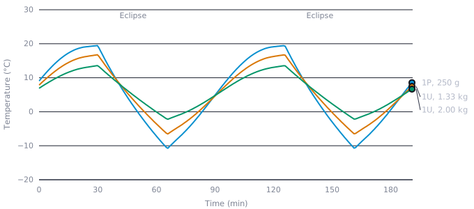
Show the data as a table
| Time (min) | 1P, 250 g | 1U, 1.33 kg | 1U, 2.00 kg |
|---|---|---|---|
| 0 | — | — | — |
| 20 | 18.6 | 15.7 | 12.6 |
| 40 | 9.0 | 9.1 | 8.6 |
| 60 | −7.2 | −3.6 | −0.1 |
| 80 | −2.4 | −0.7 | 1.3 |
| 100 | 11.9 | 10.1 | 8.5 |
| 120 | 19.1 | 16.3 | 13.1 |
| 140 | 5.0 | 6.0 | 6.6 |
| 160 | −10.0 | −5.9 | −1.8 |
| 180 | 0.7 | 1.5 | 2.7 |
| Case | Minimum (°C) | Maximum (°C) | Swing (K) | Fastest cooling (K/min) |
|---|---|---|---|---|
| 1P, 200 g | −15.0 | 21.8 | 36.8 | 1.50 |
| 1P, 250 g | −10.8 | 19.5 | 30.3 | 1.16 |
| 1U, 1.33 kg | −6.6 | 16.8 | 23.4 | 0.83 |
| 1U, 2.00 kg | −2.2 | 13.6 | 15.8 | 0.52 |
α = ε = 0.85, c_p = 858 J/(kg·K), albedo 0.30, Earth infrared 237 W/m², internal dissipation 0.25 W (1P) and 1.0 W (1U), β = 0°.
These are bulk values. External panels and poorly coupled parts swing far more: the SMOG-1 finite-element model predicted extremes of about +15 and −26 °C[8].
Surface finishes
The ratio of solar absorptance to infrared emittance sets the mean temperature; the emittance also sets how fast the body responds. For a 250 g 1P covered in one finish:
| Surface | α | ε | α/ε | Min (°C) | Mean (°C) | Max (°C) | Swing (K) |
|---|---|---|---|---|---|---|---|
| White silicate paint | 0.15 | 0.91 | 0.16 | −56 | −53 | −51 | 6 |
| Clear (sulfuric) anodize | 0.35 | 0.80 | 0.44 | −35 | −28 | −22 | 13 |
| Model surface of the review (α = ε) | 0.85 | 0.85 | 1.00 | −11 | 6 | 19 | 30 |
| Black anodize | 0.88 | 0.88 | 1.00 | −12 | 5 | 20 | 31 |
| Triple-junction cells with cover glass | 0.91 | 0.85 | 1.07 | −9 | 9 | 24 | 32 |
| Black polyurethane paint | 0.95 | 0.90 | 1.06 | −10 | 8 | 23 | 34 |
Same single-node model with representative beginning-of-life α and ε (Gilmore 2002); real spacecraft mix cells, anodized metal and boards. The ratio α/ε sets the mean temperature, the emittance how fast the body responds.
Surfaces degrade in orbit: end-of-life absorptance is higher than the data-sheet value, and hot-case analyses must use it[6][9]. A real PocketQube is mostly covered in cells, so the free choice of finish is limited to the gaps, the backplate and the antenna face.
Volume
CubeSats often have no room for , which turns thermal design largely into a coating problem[6]. PocketQubes are tighter still: cells cover most of the outer faces, leaving little surface for thermal tuning.
Thermal mass
A small satellite has little heat capacity, and its temperature changes quickly between sunlight and eclipse. At 525 km the eclipse lasts about 36 minutes, 0.63 thermal time constants of a fully loaded 1P, long enough to cool a battery below its charging limit. Heater power and control thresholds belong in the power budget from the start.
Expansion mismatch and joints
The expansion of an aluminium frame, FR-4 boards (14–17 ppm/K in plane, 50–70 ppm/K through the thickness), cell glass, germanium substrates and adhesives all differ. Over thousands of orbits the mismatch fatigues solder joints and bonds[3]. The number and position of board mounting points is a compromise between vibration and thermal stress.
Mechanism risk
Mechanisms have contributed to more than 10% of reported small-satellite failures[2]. The most effective measures are few deployables, repeated deployment tests in flight-like conditions (cold, in vacuum) and telemetry that confirms each deployment. Delfi-PQ, for example, detected separation with two independent switches[10].
Cold welding and outgassing
Bare metal surfaces in contact in vacuum can weld together, which is why is mandatory on rails and backplates. Outgassing materials can contaminate optics and neighbouring spacecraft; low- materials and a thermal-vacuum bake-out reduce the risk.
References
- [1]The CubeSat Program, Cal Poly SLO. (2022). CubeSat Design Specification, Rev. 14.1 (CP-CDS-R14.1). California Polytechnic State University.nasa.gov
- [2]NASA Small Spacecraft Systems Virtual Institute. (2026). Structures, Materials, and Mechanisms. State-of-the-Art of Small Spacecraft Technology (2026 edition), Chapter 6. NASA Ames Research Center.nasa.gov(accessed 20 October 2026)
- [3]nadir lab. (2026). A review of structural, thermal, magnetic and electronic materials in PocketQube-class picosatellites [Preprint]. nadir lab. Research Monographs (SQ-R-002).Read on nadir lab.
- [4]Kopp, G., & Lean, J. L. (2011). A new, lower value of total solar irradiance: Evidence and climate significance. Geophysical Research Letters, 38, L01706.doi:10.1029/2010GL045777
- [5]Wertz, J. R., Everett, D. F., & Puschell, J. J. (Eds.). (2011). Space Mission Engineering: The New SMAD. Microcosm Press.
- [6]NASA Small Spacecraft Systems Virtual Institute. (2026). Thermal Control. State-of-the-Art of Small Spacecraft Technology (2026 edition), Chapter 7. NASA Ames Research Center.nasa.gov(accessed 20 October 2026)
- [7]nadir lab. (2026). PocketQube-class picosatellites: architecture, flight heritage, and a multi-method post-flight analysis of Grizu-263A [Preprint]. nadir lab. Research Monographs (SQ-R-001).Read on nadir lab.
- [8]Kovács, R., & Józsa, V. (2018). Thermal analysis of the SMOG-1 PocketQube satellite. Applied Thermal Engineering, 139, 506–513.doi:10.1016/j.applthermaleng.2018.05.020
- [9]Gilmore, D. G. (Ed.). (2002). Spacecraft Thermal Control Handbook, Vol. I: Fundamental Technologies (2nd ed.). The Aerospace Press.
- [10]Uludag, M. S., Yakut, E., Speretta, S., Radu, S., Chronas-Foteinakis, N., Bouwmeester, J., Menicucci, A., & Gill, E. (2019). Getting the Delfi-PQ ready for multiple launch options. In: International Symposium on Space Technology and Science (ISTS), Fukui (2019-f-08).pure.tudelft.nl
Cite this SatWiki entry
@misc{nadirlab2026structures,
  author       = {{nadir lab.}},
  title        = {{Structures and thermal control (STR/TCS)}},
  year         = {2026},
  month        = oct,
  howpublished = {nadir lab. SatWiki SQ-SS-005 (Rev. 3)},
  url          = {https://nadirlab.space/wiki/structures-thermal/}
}
nadir lab. (2026). Structures and thermal control (STR/TCS). nadir lab. SatWiki (SQ-SS-005, Rev. 3). https://nadirlab.space/wiki/structures-thermal/
TY  - ENCYC
AU  - nadir lab.
TI  - Structures and thermal control (STR/TCS)
T2  - nadir lab. SatWiki
PY  - 2026
ET  - Rev. 3
C1  - SQ-SS-005
UR  - https://nadirlab.space/wiki/structures-thermal/
ER  -