Scenario and assumptions
We follow a 1P PocketQube in a 500 km Sun-synchronous orbit downlinking telemetry in the 437 MHz amateur-satellite band. In a 50 mm body both power and antenna placement are constrained, and a PocketQube offers roughly a quarter of the power, and therefore of the downlink capacity, of a 1U CubeSat[1][2]. The link has no margin to waste.
On the spacecraft we assume a transmitter with 0.5 W of RF output and a deployed tape-spring antenna.10.5 W of RF needs about 1.25 W of DC from a 40%-efficient amplifier. With half a watt of orbit-average power, a 1P can transmit only at a duty cycle of a few per cent; the power budget article has the details. Because the spacecraft tumbles, we take the antenna gain as 0 dBi in every direction and reserve 3 dB for pattern nulls. The ground station uses a 14 dBic crossed Yagi with a mast-mounted LNA and a system noise temperature of 500 K. The linear spacecraft antenna and the circular ground antenna cost 3 dB of polarization mismatch.
| Orbital period | 94.6 | min |
|---|---|---|
| Orbital velocity | 7.61 | km/s |
| Revolutions per day | 15.2 | |
| Longest eclipse (β = 0°) | 35.8 min, 37.8% of the orbit | |
| Sun-synchronous inclination | 97.40 | ° |
| Slant range at the horizon | 2,575 | km |
| Longest pass above 0° | 11.6 | min |
| Longest pass above 10° | 7.4 | min |
| Largest Doppler shift at 437.19 MHz | ±10.29 | kHz |
| Geomagnetic field, equator to pole | 24–47 | µT |
| Air density, low to high solar activity | 1.4 × 10⁻¹³ – 1.6 × 10⁻¹² | kg/m³ |
Two-body circular orbit over a spherical Earth; centred-dipole field; Kennewell density model.
The link equation
Written in decibels, the carrier-to-noise-density ratio at the receiver input is a sum of terms. It is the Friis transmission formula[3] extended with losses and noise[4]:
with transmit power , transmit line loss , transmit antenna gain , pointing allowance , polarization mismatch , atmospheric and ionospheric loss , the station’s figure of merit and Boltzmann’s constant dBW/(K·Hz). For a digital link the quantity that matters is the energy per bit:
The free-space loss grows with the square of distance and frequency,
and the distance depends strongly on elevation. For a spherical Earth, a satellite at altitude seen at elevation is at a slant range
| Elevation (°) | Slant range (km) | Free-space loss (dB) | Extra loss vs. zenith (dB) | Overhead pass above this elevation (min) |
|---|---|---|---|---|
| 0 | 2,575 | 153.5 | 14.2 | 11.6 |
| 5 | 2,078 | 151.6 | 12.4 | 9.2 |
| 10 | 1,695 | 149.8 | 10.6 | 7.4 |
| 20 | 1,193 | 146.8 | 7.6 | 4.9 |
| 30 | 910 | 144.4 | 5.2 | 3.5 |
| 45 | 683 | 142.0 | 2.7 | 2.1 |
| 60 | 571 | 140.4 | 1.1 | 1.2 |
| 90 | 500 | 139.2 | 0.0 | — |
Spherical Earth. Halving the distance gains 6 dB, and most of the range penalty is paid below 20° elevation.
From 500 km at zenith to 2575 km at the horizon, the path loss changes by about 14 dB within one pass.
The budget, line by line
The table is computed for 10° elevation, a typical working point of a low pass, and 9600 bit/s. The required follows from a bit error rate of 10⁻⁵ for non-coherent binary , [5], plus a 2 dB implementation loss.
| Item | Value | Unit |
|---|---|---|
| Spacecraft transmitter | ||
| Frequency | 437.200 | MHz |
| Transmit power (0.5 W) | −3.0 | dBW |
| Line and connector loss | −0.5 | dB |
| Antenna gain | 0.0 | dBi |
| EIRP | −3.5 | dBW |
| Propagation path | ||
| Elevation | 10 | ° |
| Slant range | 1,695 | km |
| Free-space path loss | −149.8 | dB |
| Polarization mismatch | −3.0 | dB |
| Atmospheric and ionospheric loss | −1.0 | dB |
| Pointing and pattern-null allowance | −3.0 | dB |
| Received power, isotropic | −160.4 | dBW |
| Ground receiver | ||
| Antenna gain | 14.0 | dBi |
| System noise temperature | 500 | K |
| G/T | −13.0 | dB/K |
| Demodulation | ||
| Boltzmann constant | −228.6 | dBW/(K·Hz) |
| C/N₀ | 55.3 | dB-Hz |
| Data rate, 9,600 bit/s | 39.8 | dB-Hz |
| Eb/N₀ | 15.4 | dB |
| Required Eb/N₀, non-coherent 2-FSK, BER 10⁻⁵ | 13.4 | dB |
| Implementation loss | 2.0 | dB |
| Link margin | +0.1(margin below 3 dB) | dB |
Reference case: 0.5 W into a 0 dBi monopole at 437.2 MHz from 500 km, a 14 dBi Yagi with a 500 K system and 9600 bit/s. A margin of 3 dB or more is the usual target for an uncoded link.
The result is a warning: the link closes on paper, but by only +0.1 dB. A deeper pattern null than expected, an interference source near the station or a slightly higher noise temperature erases it. Margins below 3 dB are not considered reliable in practice.
Elevation and data rate
The same link at other elevations:
| Elevation (°) | Slant range (km) | Free-space loss (dB) | Eb/N₀ (dB) | Margin (dB) |
|---|---|---|---|---|
| 0 | 2,575 | 153.5 | 11.8 | −3.6(link does not close) |
| 5 | 2,078 | 151.6 | 13.7 | −1.7(link does not close) |
| 10 | 1,695 | 149.8 | 15.4 | +0.1(margin below 3 dB) |
| 20 | 1,193 | 146.8 | 18.5 | +3.1(positive margin) |
| 30 | 910 | 144.4 | 20.8 | +5.5(positive margin) |
| 45 | 683 | 142.0 | 23.3 | +8.0(positive margin) |
| 60 | 571 | 140.4 | 24.9 | +9.5(positive margin) |
| 90 | 500 | 139.2 | 26.0 | +10.7(positive margin) |
Same link as the full budget; only the slant range changes with elevation.
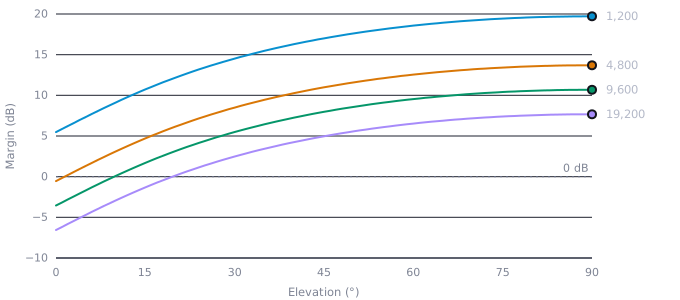
Each halving of the data rate adds 3 dB:
- 1,200 bit/s
- 4,800 bit/s
- 9,600 bit/s
- 19,200 bit/s
Show the data as a table
| Elevation (°) | 1,200 bit/s | 4,800 bit/s | 9,600 bit/s | 19,200 bit/s |
|---|---|---|---|---|
| 5 | 7.3 | 1.3 | −1.7 | −4.7 |
| 10 | 9.1 | 3.1 | 0.1 | −2.9 |
| 15 | 10.7 | 4.7 | 1.7 | −1.3 |
| 20 | 12.2 | 6.1 | 3.1 | 0.1 |
| 30 | 14.5 | 8.5 | 5.5 | 2.5 |
| 45 | 17.0 | 11.0 | 8.0 | 5.0 |
| 60 | 18.6 | 12.5 | 9.5 | 6.5 |
| 75 | 19.4 | 13.4 | 10.4 | 7.4 |
| 90 | 19.7 | 13.7 | 10.7 | 7.7 |
At 9.6 kbit/s the link reaches 3 dB only above about 20°; at 1.2 kbit/s it keeps more than 5 dB at the horizon. A fixed rate either wastes high passes or loses low ones.
What a pass delivers
Integrating over a whole pass, with at least 3 dB of margin:
| Maximum elevation | Above the horizon (min) | Margin ≥ 3 dB (min) | Raw data (kB) |
|---|---|---|---|
| 10° | 9.0 | 0.0 | 0 |
| 20° | 10.5 | 0.9 | 68 |
| 30° | 11.0 | 3.6 | 262 |
| 45° | 11.4 | 4.6 | 329 |
| 60° | 11.5 | 4.9 | 350 |
| 90° | 11.6 | 5.0 | 362 |
Channel bits before framing, coding and protocol overhead; Earth rotation neglected. Low passes, the most frequent kind, deliver little or nothing.
A pass that peaks at 10° delivers nothing at 9.6 kbit/s, although it is the most frequent kind. A station at mid-latitude sees only a few passes a day above 10°, so a mission that needs data volume must use the high passes fully and the low ones at a lower rate.
The cliff
Without forward error correction a frame is lost as soon as one bit is wrong. For 256-byte -style frames:
| Eb/N₀ (dB) | BER, coherent BPSK | BER, non-coherent 2-FSK | Frames lost, 2-FSK, 256 bytes |
|---|---|---|---|
| 8 | 1.9 × 10⁻⁴ | 2.1 × 10⁻² | 100% |
| 9 | 3.4 × 10⁻⁵ | 9.4 × 10⁻³ | 100% |
| 10 | 3.9 × 10⁻⁶ | 3.4 × 10⁻³ | 100% |
| 11 | 2.6 × 10⁻⁷ | 9.2 × 10⁻⁴ | 84.9% |
| 12 | 9.0 × 10⁻⁹ | 1.8 × 10⁻⁴ | 31.0% |
| 13 | 1.3 × 10⁻¹⁰ | 2.3 × 10⁻⁵ | 4.6% |
| 14 | < 10⁻¹² | 1.8 × 10⁻⁶ | 0.36% |
| 15 | < 10⁻¹² | 6.8 × 10⁻⁸ | 0.01% |
| 16 | < 10⁻¹² | 1.1 × 10⁻⁹ | < 0.01% |
Without forward error correction a frame is lost when any bit is wrong, so frame loss goes from almost none to almost all within about 3 dB.
Within 3 dB the link goes from losing almost every frame to losing almost none. Below the cliff more transmit power is wasted; above it, extra margin buys little. Forward error correction moves the cliff several decibels down.
A flown budget: Grizu-263A
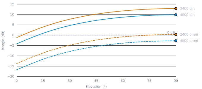
Grizu-263A transmitted 2-FSK at 4800 Bd on 437.190 MHz and 2400 Bd on 435.675 MHz with a coordinated of 20 dBm: 100 mW into a 0 dBi monopole, a fifth of the power of our reference transmitter. The PocketQube review evaluated it against a directional station (13 dBic, 350 K) and an omnidirectional one (2 dBic, 500 K)[1]. The nadir lab. model reproduces its numbers:
| Item | Value | Unit |
|---|---|---|
| Spacecraft transmitter | ||
| Frequency | 437.190 | MHz |
| Transmit power (0.1 W) | −10.0 | dBW |
| Line and connector loss | 0.0 | dB |
| Antenna gain | 0.0 | dBi |
| EIRP | −10.0 | dBW |
| Propagation path | ||
| Elevation | 30 | ° |
| Slant range | 951 | km |
| Free-space path loss | −144.8 | dB |
| Polarization mismatch | −3.0 | dB |
| Atmospheric and ionospheric loss | −0.5 | dB |
| Pointing and pattern-null allowance | −1.0 | dB |
| Received power, isotropic | −159.3 | dBW |
| Ground receiver | ||
| Antenna gain | 13.0 | dBi |
| System noise temperature | 350 | K |
| G/T | −12.4 | dB/K |
| Demodulation | ||
| Boltzmann constant | −228.6 | dBW/(K·Hz) |
| C/N₀ | 56.8 | dB-Hz |
| Data rate, 4,800 bit/s | 36.8 | dB-Hz |
| Eb/N₀ | 20.0 | dB |
| Required Eb/N₀, non-coherent 2-FSK, BER 10⁻⁵ | 13.4 | dB |
| Implementation loss | 2.0 | dB |
| Link margin | +4.7(positive margin) | dB |
Grizu-263A: coordinated EIRP of 20 dBm, 3 dB polarization, 0.5 dB atmospheric and 1 dB pointing and cable losses, 2 dB implementation loss (review, Table 7).
- Directional, 4800 Bd
- Directional, 2400 Bd
- Omnidirectional, 4800 Bd
- Omnidirectional, 2400 Bd
Show the data as a table
| Elevation (°) | Directional, 4800 Bd | Directional, 2400 Bd | Omnidirectional, 4800 Bd | Omnidirectional, 2400 Bd |
|---|---|---|---|---|
| 5 | −2.4 | 0.7 | −14.9 | −11.9 |
| 10 | −0.7 | 2.4 | −13.2 | −10.2 |
| 15 | 0.9 | 4.0 | −11.6 | −8.6 |
| 20 | 2.3 | 5.4 | −10.2 | −7.2 |
| 30 | 4.7 | 7.7 | −7.9 | −4.8 |
| 45 | 7.1 | 10.2 | −5.4 | −2.4 |
| 60 | 8.7 | 11.7 | −3.9 | −0.8 |
| 75 | 9.6 | 12.6 | −3.0 | 0.0 |
| 90 | 9.8 | 12.9 | −2.7 | 0.3 |
At 4800 Bd only directional stations above about 12° could decode; the 2400 Bd mode gained 3 dB, reaching directional stations down to 3° and omnidirectional ones only near zenith. The dual-rate design traded throughput for accessibility, and the small margins match the observation that many recordings in the first days lacked the signal-to-noise ratio for decoding.
Strategies
Three measures move a power-limited link from marginal to robust:
- Adaptive data rate. Switching between, say, 1.2 and 9.6 kbit/s with elevation or with ground feedback turns low passes from useless into useful. Grizu-263A’s two modes were a fixed version of this idea.
- Forward error correction. A convolutional or Reed–Solomon code gains several decibels at the cost of bandwidth and processing, and moves the frame-loss cliff down.
- Better ground stations. A mast-mounted LNA and a higher-gain antenna raise ; the G/T article shows by how much.
Propagation effects stay small at UHF: gaseous and rain losses, which ITU-R P.618 quantifies for higher bands, are negligible here[6], while Faraday rotation is absorbed by the circular ground antenna. Open networks multiply the passes a mission can use: stations around the world record every pass they schedule[7].
Conclusion
A 0.5 W UHF downlink from a 1P closes comfortably on high passes and barely or not at all on low ones at 9.6 kbit/s. The data volume a PocketQube returns is set by its energy per bit, not by its radio’s nominal rate; adaptive rates, coding and open ground networks are the levers that turn that energy into data.