Materials engineering for PocketQube picosatellites: A scaling-based review and design guide
- Research group
- nadir lab.
- Published
- 20 October 2026
- Version
- nadir lab. Monograph REV 0.1, 20 October 2026
- Identifier
- SQ-R-002
- Reading time
- 66 min
- Licence
- CC BY-NC-ND 4.0
At a glance
- of the moment of inertia of a 1U CubeSat carried by a 1P PocketQube
- 3–5%
- stronger stray field of a fixed-moment magnet at the inner walls
- 8×
- lumped eclipse temperature swing of a 1P unit, against 16–23 K for a 1U
- 30–37 K
- median life of rigid FR-4/germanium solder joints in the Engelmaier screening
- ≈1 year
Highlights
- Scaling laws show which CubeSat materials practices break down at PocketQube scale
- 7075-T6 backplates require stress-corrosion justification under ECSS rules
- 1P hysteresis dampers are limited by demagnetization and magnet bias, not saturation
- Coercivity sets a despin-versus-dead-band trade-off; hybrid damper sets are proposed
- Thermal swings of 30–37 K plus FR-4 CTE mismatch can cap solder life near one year
Abstract
PocketQubes, modular picosatellites built from 50 mm cubic units of at most 250 g, have now passed one hundred launched spacecraft, yet their materials engineering is still largely inherited from CubeSats. This review examines that inheritance through an explicit scaling framework. Halving the cube edge reduces the principal moment of inertia to 3–5% of that of a 1U CubeSat and the thermal inertia per unit area to 50–75%, leaves gravity-gradient effects unchanged, and raises the stray field of an internal magnet at the walls eightfold. These shifts are traced through four coupled materials domains. For the 1.6 mm sliding backplate, the dominant risks are interfacial rather than structural: stress-corrosion susceptibility of peak-aged 7075, fretting-induced cold welding, and the dimensional and fatigue penalties of hard anodizing. For passive magnetic attitude control, closed-form demagnetization models show that soft-magnetic dampers in a 1P unit are limited by geometry and by magnet-induced bias rather than by saturation, and that coercivity governs a trade-off between despin rate and a residual pointing dead band; hybrid sets of stress-free Fe-based amorphous strips and 80% Ni–Fe elements are therefore proposed. For electronics, a lumped orbital model predicts eclipse swings of 30–37 K, and an Engelmaier screening shows that FR-4/germanium expansion mismatch can limit solder-joint life to about one year. Outgassing and atomic-oxygen data for laminates and additively manufactured polymers are compiled. The review closes with a verification-oriented design matrix and a prioritized list of research gaps.
- PocketQube
- Picosatellite
- Space materials
- Cold welding
- Passive magnetic attitude control
- Outgassing
Contents
Full text
1. Introduction#
1.1. PocketQubes and the inherited materials baseline#
The PocketQube was conceived in 2009 at Morehead State University and Kentucky Space as a picosatellite format occupying one eighth of the volume of a 1U CubeSat [1, 2]. The current mechanical standard, issued jointly by Delft University of Technology, Alba Orbital and GAUSS Srl, defines a unit (1P) as a 50 mm cube with a mass not exceeding 250 g; 2P and 3P configurations are limited to 500 g and 750 g, respectively [3]. Instead of the four corner rails of a CubeSat, a PocketQube is held and ejected by a single 1.6 mm sliding backplate clamped along two edges by the deployer [3]. The first PocketQubes reached orbit in 2013 [4], more than one hundred had been launched by April 2026 [5], and the current population spans masses of 125–850 g, all of it in low Earth orbit (LEO) [1]. A survey of 52 missions launched between 2013 and 2024 found that 51% used the 1P form factor and that 27 relied on passive, magnetic-only attitude control [6]. One of the best-documented missions, the 3P Delfi-PQ (545 g), operated for almost two years after its launch on 13 January 2022 and re-entered in January 2024, experiencing thermal swings of up to 75 °C [7].
These numbers frame the problem addressed here. Most PocketQube teams build with commercial terrestrial components [8], and their materials choices are, explicitly or implicitly, inherited from three sources: the CubeSat Design Specification (CDS) for rails, coatings and outgassing [9]; European Cooperation for Space Standardization (ECSS) standards for stress-corrosion cracking (SCC) and outgassing, which the PocketQube Standard cites [3, 10, 11]; and passive-magnetic design rules developed for 1U–3U CubeSats and microsatellites [12–14]. Each of these sources was derived for a different length scale. Because area, volume, inertia, thermal capacitance and magnetic near fields scale with different powers of the characteristic length, a rule that is conservative for a CubeSat can be inadequate, irrelevant or unnecessarily restrictive for a PocketQube.
1.2. Existing reviews and the gap addressed#
Bouwmeester et al. quantified the utility and constraints of PocketQubes—power, downlink, lifetime and cost—and noted the high ratio of outer surface to internal heat capacity that complicates thermal control [8]. Franzese surveyed missions and enabling technologies and identified propulsion as the key technology for future missions [1]. Idriss and Ismail reviewed attitude determination and control across 52 missions [6], Valencia et al. reviewed additive manufacturing (AM) of PocketQube structures against ECSS qualification requirements [5], and Silva et al. reviewed MEMS micropropulsion for CubeSats and PocketQubes [15]. None of these works examines, within a single framework, how the change of scale alters the physics that governs materials selection across subsystems—the tribology of the sliding interface, the magnetics of passive dampers, the thermomechanics of electronics and the contamination behaviour of polymers—or tests the material clauses of the PocketQube Standard against the ECSS documents it invokes.
1.3. Contributions, scope and conventions#
This review makes six contributions:
- (i) a scaling framework that quantifies ten materials-relevant ratios between a 1P PocketQube and a 1U CubeSat, both under geometric similarity and at the mass and centre-of-mass limits of the two standards (Section 2);
- (ii) a critical reading of the PocketQube Standard material clauses against ECSS-Q-ST-70-36C and ECSS-Q-ST-70-02C, which identifies an unspecified temper for 7075 and a total-mass-loss criterion that differs from the ECSS recovered-mass-loss criterion (Sections 3 and 7);
- (iii) an analysis of the sliding backplate as an interface-critical rather than strength-critical component, covering cold welding and the dimensional and fatigue effects of hard anodizing (Sections 3 and 4);
- (iv) a closed-form treatment of hysteresis damping in the demagnetization-limited regime, including the scaling of despin time, the tolerance of dampers to magnet-induced bias and the coercivity dead band (Section 5);
- (v) a coupled screening of orbital temperature swings and solder-joint fatigue that links thermal capacitance to expansion mismatch (Section 6), together with compiled outgassing and atomic-oxygen data (Section 7);
- (vi) a design-and-verification matrix and a prioritized research agenda (Section 9).
The scope is limited to LEO missions of up to 3P. The models are deliberately first-order: they are intended to rank options and to expose scale effects during trade studies, not to replace analysis or qualification testing. Property values are typical room-temperature values from the cited sources, and design allowables must be taken from qualified databases or supplier certificates. SI units are used throughout; where the PocketQube Standard is quoted, requirement identifiers (e.g. PQ-Mat-03) refer to Issue 1 [3].
2. A scaling framework for PocketQube materials#
Let denote the cube edge and the ratio between a 1P PocketQube and a 1U CubeSat. Under geometric similarity at constant bulk density, mass and internal volume scale as , the external area—and with it the body-mounted solar power—as , and the principal moment of inertia of a homogeneous cube,
as . The standards, however, do not impose geometric similarity. The 1P ceiling of 250 g [3] corresponds to a bulk density of 2.0 g cm⁻³, whereas the 1.33 kg limit long applied to 1U CubeSats corresponds to 1.33 g cm⁻³ (CDS Revision 14.1 now allows 2.00 kg [9]). At the mass limits, the inertia ratio is therefore 0.047 rather than 0.031 (Fig. 1). Either way, a PocketQube carries 3–5% of the inertia of a 1U CubeSat, which is the quantity that matters for detumbling, for the response to disturbance torques and for the energy that passive dampers must dissipate (Section 5). Orbit-average power for a body-mounted 1P is a few hundred milliwatts [8], which constrains active thermal and attitude control and makes passive, materials-based solutions attractive.
Disturbance torques do not follow inertia. The aerodynamic torque,
where is the atmospheric density, the orbital velocity, the drag coefficient, the projected area and the offset between the centres of pressure and mass, scales as when . The resulting angular acceleration is four times larger in a PocketQube; with the centre-of-mass tolerances of the two standards (1 cm for PocketQubes, PQ-Mass-04 [3]; 2 cm for a 1U, CDS Table 2 [9]) the factor is 2.7. Solar radiation pressure follows the same area-times-lever-arm scaling. In contrast, the gravity-gradient torque,
is proportional to a difference of inertias, so the angular acceleration it produces depends only on inertia ratios and on the orbit. Gravity gradient is therefore not intrinsically more important for a PocketQube than for a CubeSat of similar proportions. Torques that do not scale with size at all—most notably that of the residual magnetic dipole of the electronics—become relatively more important as decreases.
The areal density controls two materials-relevant quantities: the thermal inertia per unit radiating area, , which sets the amplitude of eclipse temperature swings (Section 6), and the mass thickness that a fixed structural mass fraction can provide as radiation shielding. It falls to 0.5 under similarity and to 0.75 at the mass limits. Its inverse, the area-to-mass ratio, governs drag and radiation-pressure accelerations and therefore orbital lifetime [8]. For passive magnetic attitude control, the internal length available to a soft-magnetic damper shrinks from about 95 mm [12] to about 45 mm, while the field of a permanent magnet of given dipole moment, which decays as , is eight times stronger at the internal walls (Fig. 1). Sections 3–8 trace these ratios into the individual materials domains; Table 1 first summarizes the requirements of the PocketQube Standard that bear directly on materials.
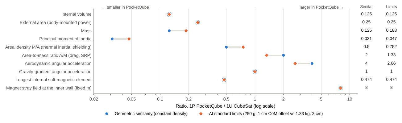
Materials-relevant ratios between a 1P PocketQube and a 1U CubeSat. Circles assume geometric similarity at constant bulk density; diamonds use the limits of the two standards (250 g and a 1 cm centre-of-mass tolerance [3] versus 1.33 kg and 2 cm [9]). Where only one marker is visible, both assumptions give the same ratio. The longest soft-magnetic element compares 45 mm with the 95 mm available in a 1U unit [12]; the stray field compares a magnet of fixed dipole moment at half the distance.
Table 1.PocketQube Standard (Issue 1) requirements with direct materials implications [3].
| Requirement | Content (abridged) | Materials implication |
|---|---|---|
| PQ-Gen-02 | No pyrotechnics on board | Release by thermal knives or shape-memory devices; cutting filaments must satisfy outgassing limits |
| PQ-Gen-03 | No toxic, flammable or hazardous materials; Li-ion cells exempt if thermal runaway is prevented | Magnesium alloys, beryllium and some polymers require launch-provider (LSP) consultation; battery protection and test evidence |
| PQ-Gen-04 | Outgassing: TML ≤ 1.0%, CVCM ≤ 0.1% “per ECSS-Q-70-02C” | ECSS-Q-ST-70-02C screens on RML, not TML (Section 7) |
| PQ-Mech-01–07 | 1P body 50.0 ± 0.1 mm; backplate 58.0 × 64.0 mm, t = 1.6 mm; 2 mm rail-clamped edges | Coating growth and flatness consume tolerance; edges are fretting contacts (Section 4) |
| PQ-Mech-08 | External components within a 7 mm envelope | Limits deployable structures, antennas and external magnets |
| PQ-Mech-10, -12–15 | Contact surface on the Z+ face; at least two kill switches at the Z− end touching rails or the neighbouring unit | Additional metal-to-metal or metal-to-polymer contacts under preload |
| PQ-Mass-01–04 | 250/500/750 g; centre of mass within 1 cm of the geometric centre | Mass budget drives material density; offset sets aerodynamic torque (Eq. (2)) |
| PQ-Mat-01 | Structure withstands all environmental tests | Qualification by test rather than by analysis alone |
| PQ-Mat-02 | Recommended: FR-4 and Al 7075, 6061, 6065, 6082 per ECSS-Q-ST-70-36C | No temper specified; 7075-T6 is a low-SCC-resistance temper (Section 3) |
| PQ-Mat-03 | Hard anodizing of metallic parts contacting deployer or standoffs | Film thickness, alloy response, fatigue debit, electrical isolation (Section 4) |
| PQ-Mat-04 | Other materials require LSP consultation | Applies to Mg, Ti, steels, AM metals and most polymers |
3. Structural materials and the sliding-backplate interface#
3.1. An interface-critical component#
The sliding backplate concentrates the entire mechanical interface of a PocketQube in a plate 1.6 mm thick: for a 1P unit it measures 58.0 × 64.0 mm, of which a 2 mm strip along each lateral edge is clamped by the deployer rails (PQ-Mech-07); the corresponding plate lengths are 128 mm for 2P and 192 mm for 3P units [3] (Fig. 2a). Bulk stresses in this plate are small. For an illustrative quasi-static load factor of 20 g—launcher-specific values must be taken from the user’s guide of the launch service—a 250 g unit exerts 49 N, which corresponds to a mean bearing pressure of 0.19 MPa on the 256 mm² of clamped area, more than two orders of magnitude below the strength of any candidate material in Table 2. The unsupported span between the clamped strip and the body footprint is only about 2 mm. The plate is therefore governed less by strength than by flatness, thickness and width tolerance, edge condition, surface hardness and the tribology of the clamped strips, all of which are set by the choice of alloy, temper and coating (Section 4).
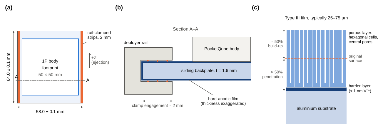
The PocketQube sliding-backplate interface. (a) Plan view of a 1P backplate with the rail-clamped strips and the body footprint [3]. (b) Schematic section A–A through one rail clamp; triangles mark fretting contacts under launch vibration and the hard-anodic film is drawn exaggerated. (c) Structure of a porous (Type III) anodic film: a compact barrier layer whose thickness scales with the forming voltage, beneath columnar hexagonal cells with central pores; roughly half of the film grows outward from the original surface [16–18].
3.2. Aluminium alloy metallurgy and stress-corrosion classification#
PQ-Mat-02 recommends FR-4 and the aluminium alloys 7075, 6061, 6065 and 6082 “per ECSS-Q-ST-70-36C” [3]; the CDS lists 7075, 6061, 6082, 5005 and 5052 for CubeSat structures [9]. Neither document specifies a temper, although the temper determines both strength and SCC susceptibility.
In 6xxx (Al–Mg–Si) alloys, artificial ageing of the supersaturated solid solution proceeds through solute clusters and Guinier–Preston zones to needle-shaped β″ precipitates, which provide the peak (T6) strength, and then to β′ and equilibrium β-Mg₂Si [19]; the β″ phase has the composition Mg₅Si₆ [20]. These alloys combine moderate strength (yield strength of 260–276 MPa for 6082-T6 and 6061-T6) with good machinability, a uniform anodizing response and high SCC resistance: ECSS-Q-ST-70-36C places the whole 6000 series, in all tempers, in its high-resistance Table 5-1 [10], which also covers 6065.
In 7xxx (Al–Zn–Mg–Cu) alloys, Guinier–Preston zones transform into the semi-coherent η′ phase responsible for peak strength and, on further ageing, into equilibrium η-MgZn₂ [21]. The peak-aged T6 temper reaches a yield strength of about 500 MPa but is susceptible to intergranular SCC, particularly under short-transverse tension, through the combined action of grain-boundary precipitates, precipitate-free zones and hydrogen [22, 23]. Over-ageing to T73 or T7351 coarsens the grain-boundary η particles and restores SCC resistance at a strength penalty of roughly 10–15% [24]. ECSS-Q-ST-70-36C accordingly classifies 7075-T73 as highly resistant (Table 5-1), 7075-T76 as moderately resistant (Table 5-2) and 7075-T6, like 2024-T3, as having low resistance (Table 5-3) [10]. Table 5-3 alloys may be considered only where the probability of stress corrosion is remote and require a customer-approved stress-corrosion evaluation form (SCEF); Table 5-2 alloys in sheet thinner than 6.5 mm are exempt from the SCEF [10]. Two practical conclusions follow. First, a 7075-T6 backplate—the most readily available temper of the alloy listed in PQ-Mat-02—formally requires an SCEF under the standard that PQ-Mat-02 invokes, whereas a 7075-T73 or T7351 plate does not, and a 7075-T76 plate qualifies for the thin-sheet exemption. Second, because the backplate is not strength-critical (Section 3.1), the strength advantage of 7075 is largely irrelevant at this interface; 6061-T6 or 6082-T6 provide the same function with high SCC resistance and a more uniform hard-anodic film. A future revision of PQ-Mat-02 could remove the ambiguity by specifying tempers (e.g. 6061-T6, 6082-T6, 7075-T73/T7351).
Table 2.Typical room-temperature properties of candidate structural materials and their status under ECSS-Q-ST-70-36C and the PocketQube Standard.
| Material | (g cm⁻³) | (GPa) | (MPa) | (MPa) | (10⁻⁶ K⁻¹) | (W m⁻¹ K⁻¹) | SCC classᵃ | PQ statusᵇ |
|---|---|---|---|---|---|---|---|---|
| Al 6061-T6 | 2.70 | 68.9 | 276 | 310 | 23.6 | 167 | High | Mat-02 |
| Al 6082-T6 | 2.70 | 70.0 | 260 | 310 | 23.4 | 172 | High | Mat-02 |
| Al 7075-T6 | 2.81 | 71.7 | 503 | 572 | 23.4 | 130 | Low | Mat-02ᶜ |
| Al 7075-T73 | 2.81 | 72.0 | 435 | 505 | 23.4 | 155 | High | Mat-02ᶜ |
| Al 2024-T3 | 2.78 | 73.1 | 345 | 483 | 23.2 | 121 | Low | Mat-04 |
| AlSi10Mg, LPBF as built (XY) | 2.67 | ≈70 | 270 | 461 | – | – | n.l.ᵈ | Mat-04 |
| Mg AZ31B-H24 | 1.77 | 45.0 | 220 | 290 | 26.0 | 96 | n.l. | Gen-03, Mat-04 |
| Ti-6Al-4V, annealed | 4.43 | 113.8 | 880 | 950 | 8.6 | 6.7 | High | Mat-04 |
| 17-7PH, TH1050 | 7.64 | 204 | 1170 | 1310 | 11.0 | 16.4 | cond.ᵉ | Mat-04 |
| FR-4, in plane | 1.85 | ≈22 | – | ≈300 | 14–17ᶠ | 0.3 | – | Mat-02 |
| Windform XT 2.0, SLS | 1.10 | 8.93 | – | 83.8 | – | – | – | Mat-04 |
| PEEK, unfilled | 1.30 | ≈3.8 | ≈98 | – | ≈47 | 0.25 | – | Mat-04 |
| ULTEM 9085, FDM (XZ) | 1.34 | 2.15 | 47 | 69 | 65 | – | – | Mat-04 |
Sources: wrought alloys [25, 26]; AlSi10Mg [27]; FR-4 [28]; Windform XT 2.0 [29]; PEEK [30]; ULTEM 9085 [31]. Design allowables must be taken from qualified sources. ᵃ ECSS-Q-ST-70-36C: High = Table 5-1, Low = Table 5-3 [10]; n.l. = not listed in Table 5-1. ᵇ PocketQube Standard Issue 1 [3]: Mat-02 = recommended; Mat-04 = LSP consultation; Gen-03 = hazardous/flammable materials clause. ᶜ Listed as “7075” without temper. ᵈ Cast Al–Si(–Mg) alloys such as A356.0 are high-resistance in Table 5-1; LPBF AlSi10Mg is not listed as such. ᵉ Precipitation-hardening steels are classified by heat-treatment condition. ᶠ Out-of-plane (z) expansion below is typically 50–70 ppm K⁻¹.
3.3. Mass efficiency of panels and of the backplate#
For panels of free thickness loaded in bending—side walls, PCB-based structures, solar-panel substrates—the mass-minimizing material indices are for stiffness and for strength [30]. Fig. 3(a) shows that, on these indices, the wrought and AM aluminium alloys cluster together, magnesium AZ31B and the SLS composite Windform XT 2.0 lead in stiffness, and FR-4 leads in strength, whereas Ti-6Al-4V and 17-7PH are penalized by density. This explains why PCB-as-structure designs are mass-efficient: the 1P SMOG-1 PocketQube, for instance, has no separate frame, its printed circuit boards and threaded rods carrying the loads [32]. The price is a coupling of structural, thermal and electrical design: FR-4 has a thermal conductivity more than two orders of magnitude below that of aluminium and an expansion coefficient mismatched to both aluminium and semiconductor substrates (Section 6). The backplate is a different case because its thickness is fixed by the standard. Its mass then scales with density alone: a solid plate weighs 11.0 g in FR-4, 16.0 g in 6061-T6, 16.7 g in 7075-T73, 26.3 g in Ti-6Al-4V and 45.4 g in 17-7PH, that is, from 4.4% to 18.2% of the 1P mass budget (Fig. 3b). The flexural rigidity ranges from 7.6 N m for FR-4 to 26.4 N m for 6061-T6 (Fig. 3c). FR-4 saves about 5 g—2% of the 1P budget—at the cost of a 3.5-fold lower rigidity, of potential resin creep under rail preload at elevated temperature and of a fretting behaviour against deployer rails that has not, to the author’s knowledge, been documented in the open literature. Aluminium therefore remains the conservative choice for the backplate, and AA6061-T6 is, in practice, the de facto structural alloy of PocketQubes [5].
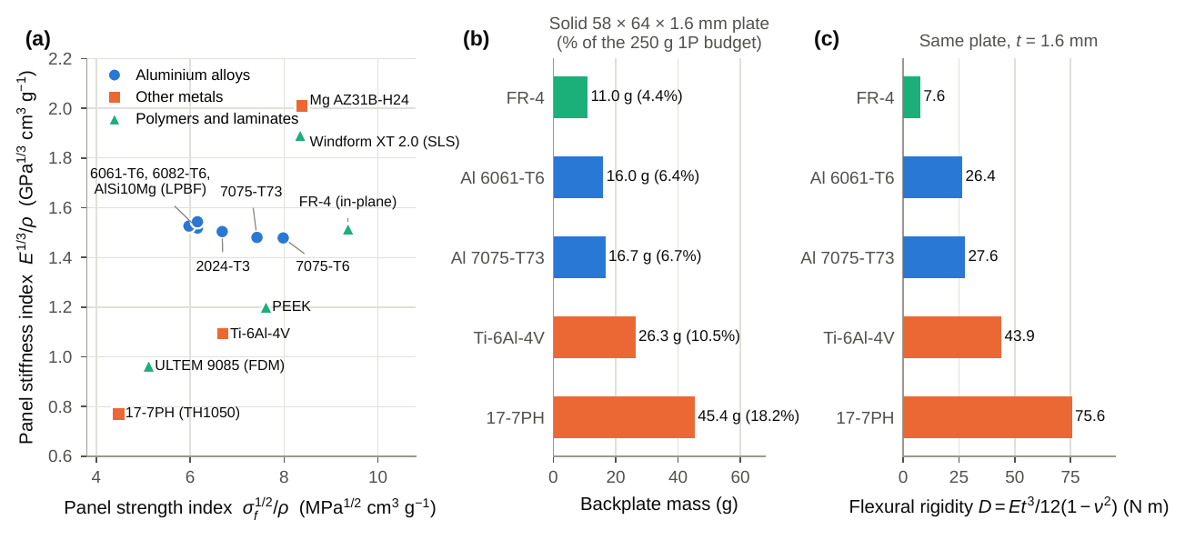
(a) Mass-efficiency indices for panels in bending ( is the yield strength of metals and the tensile strength of the non-metals); the three coincident aluminium grades share a label. (b) Mass of a solid 1P backplate (58 × 64 × 1.6 mm, 5.94 cm³) and its share of the 250 g budget. (c) Flexural rigidity of the same plate. Property data as in Table 2.
3.4. Alternative metals and additively manufactured structures#
Magnesium alloys offer the highest panel stiffness index (Fig. 3a) but fall under the flammability clause PQ-Gen-03 and require LSP consultation (PQ-Mat-04) [3]; they also corrode readily and are absent from the high-resistance SCC table [10]. Ti-6Al-4V and precipitation-hardening steels are uneconomical in mass for plates but are appropriate for inserts, fasteners and hinge pins, where thread strength and galling resistance matter more than density. Among AM metals, laser powder-bed-fused (LPBF) AlSi10Mg reaches as-built yield strengths of 233–270 MPa at a density of at least 2.67 g cm⁻³ [27], comparable with 6061-T6, and topology-optimized AM structures promise mass reductions of 30–60% [5]. Their as-built roughness and Si-rich microstructure, however, complicate hard anodizing (Section 4), and qualification readiness lags behind technological maturity: ECSS-Q-ST-70-80C provides no de-rated qualification pathway for parts below 100 g [5]. AM polymers and composites, notably the carbon-filled polyamide Windform XT 2.0 used for the AlbaPod v2 deployer [33], are discussed in Section 7.
4. Vacuum tribology: cold welding, fretting and hard anodizing#
4.1. Mechanism and relevance to PocketQube deployers#
In air, metal surfaces are covered by native oxides and adsorbed layers that prevent metallic bonding between contacting asperities. Small-amplitude oscillatory sliding (fretting) during launch vibration, or repeated impact, disrupts these films. In vacuum the films cannot re-form fast enough, and clean metal asperities can bond by adhesion at ambient temperature—cold welding, a solid-state process that does not require bulk diffusion [34, 35]. ESA has standardized test methods that quantify the adhesion force between separable contacts after impact or fretting in vacuum [35]. Recent campaigns observed adhesion at pressures of about 1 Pa and below, where oxide regrowth no longer outpaces fretting; self-mated silver, copper and 17-7PH exceeded the 12 000 mN measurement limit, and a sputtered MoS₂ coating on 17-7PH against Ti-6Al-4V failed after about 40 fretting cycles in vacuum, with launch-like conditions shortening its life further [36]. Ground handling matters as well: fretting in air, for instance during shaker tests, changes the subsequent behaviour in vacuum [37]. The best-known flight consequence is the incomplete deployment of the Galileo high-gain antenna in 1991, attributed to cold welding of three ribs after vibration had degraded their dry-lubricant coating [36, 38].
A PocketQube deployer combines all ingredients of this failure mode: two 2 mm clamped strips per unit and the Z± contacts between stacked units and with the pusher plate (Fig. 2b), preloaded and vibrated during qualification testing in air and again during launch, then held in vacuum for hours to weeks before ejection. Any adhesion force adds to the friction that the deployer spring must overcome; the AlbaPod v2 deployer, for example, was specified for an ejection velocity of at least 2 m s⁻¹ [33]. The CDS and the PocketQube Standard both respond with the same measure, hard anodizing of aluminium contact surfaces [3, 9].
4.2. Metallurgy of hard-anodic films#
Anodizing in acidic electrolytes converts the aluminium surface into a duplex oxide film: a thin, compact barrier layer at the metal interface, whose thickness is of the order of 1 nm per volt of forming voltage, under a much thicker porous layer of close-packed hexagonal cells, each with a central pore normal to the surface [16, 17, 39] (Fig. 2c). Type III (hard) anodizing uses sulfuric-acid electrolytes near 0 °C and high current densities to grow thick, dense and hard films; such films, governed by MIL-A-8625F [18], are commonly specified at a nominal 50 µm (0.002 in) within a typical range of 25–75 µm. The film is porous rather than pore-free, and it is its ceramic character—not the absence of porosity—that suppresses adhesion: oxide-to-metal and oxide-to-oxide contacts replace metal-to-metal contact. The protection lasts only as long as the film is intact; once fretting or impact breaches it locally, bare aluminium is exposed. Vacuum fretting data for hard-anodized aluminium against the specific materials of PocketQube deployer rails appear to be scarce in the open literature, which is one of the gaps listed in Section 9.
Five secondary effects of hard anodizing are material-specific and relevant at PocketQube tolerances:
- (a) Dimensional growth. Roughly half of the film grows outward from the original surface (Fig. 2c). A 50 µm film therefore adds about 25 µm per coated face and about 50 µm to the 58.0 mm backplate width, i.e. half of the ±0.1 mm tolerance band [3]. The plate must be machined undersize by the expected growth, and the film thickness should be specified and measured (e.g. by eddy current) after coating.
- (b) Alloy response. Copper-rich 2xxx alloys and high-silicon cast or AM alloys form thinner, softer and less uniform films. For LPBF AlSi10Mg, pulsed-current hard anodizing reached a microhardness of about 280 HV0.025 at best, below that of anodized wrought alloys [40]. AM backplates or rails therefore cannot rely on the coating performance established for wrought 6xxx alloys.
- (c) Fatigue debit. In 6082 aluminium, hard anodizing reduced the high-cycle fatigue strength by 50–62%, depending on film thickness (20–70 µm), compared with 8–50% for conventional anodizing, because cracks initiate in the brittle film and propagate into the substrate [41]. This is tolerable for the lightly loaded backplate but not for anodized brackets, hinges or spring-loaded parts under cyclic stress.
- (d) Sealing and impregnation. Sealing reduces porosity and improves corrosion resistance but lowers hardness and wear resistance; PTFE-impregnated hard coats reduce friction but introduce an organic phase that must meet the outgassing requirement PQ-Gen-04 and requires LSP consent.
- (e) Electrical isolation. Anodic films are electrical insulators. They therefore isolate the spacecraft chassis from the deployer, which must be considered in the grounding and electrostatic-discharge design (bonding points are masked during anodizing). The kill switches required by PQ-Mech-12 to PQ-Mech-15 are mechanical devices whose function does not depend on the coating, although their actuators are additional contacts that share the cold-welding concern.
4.3. Recommended practice#
Combining the evidence above, the following practice is recommended for PocketQube interfaces: (i) prefer 6061-T6 or 6082-T6 for backplates and avoid self-mated identical metals at any separable contact; (ii) specify the anodizing type, thickness (typically 25–50 µm) and sealing state on the drawing, round edges (the CDS recommends rail-edge radii of at least 1 mm [9]) and machine undersize by the expected growth; (iii) control roughness of the sliding faces, for which the CDS requirement for CubeSat rails, Ra < 1.6 µm [9], is a reasonable reference; (iv) inspect film thickness, dimensions and flatness after coating; and (v) after vibration testing, perform a vacuum dwell and ejection or separation test of the flight-representative backplate–rail pair, ideally following the methodology of ESA STM-279 [35].
5. Magnetic materials for passive attitude control#
Passive magnetic attitude control (PMAC) combines a permanent magnet, which aligns one spacecraft axis with the geomagnetic field, with soft-magnetic hysteresis dampers, which convert rotational energy into heat as the field component along them cycles [13, 42]. It consumes no power and has no moving parts, which explains its prevalence among PocketQubes [6]. Its materials questions are which magnet, which soft-magnetic alloy, in which geometry and where. This section shows that the answers change qualitatively between 1U and 1P.
5.1. Magnet sizing and permanent-magnet materials#
A common sizing rule, adapted by Gerhardt and Palo from Santoni and Zelli, requires the magnetic restoring torque to exceed the root-mean-square disturbance torque by a factor at the weakest field and the largest acceptable pointing error [12, 13]:
For the 3U CSSWE CubeSat, N m, µT and gave A m² [12]. For a 1P unit at 500 km, Eq. (2) with cm², , km s⁻¹, the maximum offset cm and kg m⁻³ gives –7.9 nN m, whereas a residual dipole of 1 × 10⁻³ A m²—an assumption, since residual dipoles are rarely reported for PocketQubes—produces about 30 nN m in a 30 µT field. Eq. (4) then yields –0.3 A m²: the magnet does not shrink in proportion to the spacecraft, because the size-independent residual-dipole torque dominates.
Table 3 compares the permanent-magnet candidates. A volume of 100 mm³ delivers A m² with either AlNiCo 5 or sintered NdFeB, but the two behave very differently. AlNiCo has a low intrinsic coercivity, so its operating point depends strongly on shape: short magnets (length-to-diameter ratio near one) self-demagnetize substantially and should be elongated or stabilized [43, 44]. NdFeB has a high coercivity but a reversible temperature coefficient of remanence about six times larger, so that a 100 K swing changes its moment by roughly 12%, and standard grades are limited to about 80 °C. AlNiCo 5 and SmCo change by only 2–3.5% over the same swing. For the strong eclipse cycling of PocketQubes (Section 6), AlNiCo 5 in an elongated shape or SmCo is therefore preferable; NdFeB is acceptable in high-temperature grades if the torque margin covers its thermal drift. The Turkish 1P PocketQube Grizu-263A (237 g, launched on 13 January 2022) [45] is an example of a 1P design that combined AlNiCo 5 magnets with HyMu-80 hysteresis rods, according to its development team [46].
Table 3.Typical properties of permanent-magnet materials for PMAC [43, 44].
| Material | (T) | (kA m⁻¹) | (kJ m⁻³) | (% K⁻¹) | (°C) | (g cm⁻³) | Remarks for PocketQubes |
|---|---|---|---|---|---|---|---|
| AlNiCo 5 (cast) | 1.25–1.28 | ≈50 | ≈40 | −0.02 | ≈860 | 7.3 | Thermally stable; low coercivity, shape-sensitive working point; prefer elongated magnets |
| SmCo (2:17, sintered) | 1.0–1.15 | 1400–2400 | 190–240 | −0.03 | ≈820 | 8.4 | Most stable high-coercivity option; brittle |
| NdFeB (N42, sintered) | 1.28–1.32 | ≥955 | 320–340 | −0.12 | ≈310 | 7.5 | Largest moment per volume; ≈12% drift per 100 K; coated against corrosion; standard grades ≲80 °C |
5.2. Hysteresis damping in the demagnetization-limited regime#
A soft-magnetic element of finite length magnetized along its axis experiences an internal field , where is the applied field component along the axis, the magnetization and the axial demagnetizing factor [47]. For a cylinder of length and diameter , the magnetometric factor is well approximated by [48]
and for a rectangular strip the exact closed form of Aharoni applies [49]; it was evaluated here in extended precision, because the terms cancel strongly for ribbons 25 µm thick. Fig. 4(a) shows that a 1 mm rod limited to the 45 mm available in a 1P unit has , twice its value at the 95 mm of a 1U unit (), whereas a 25 µm × 5 mm strip of the same length has .
Because the intrinsic permeability of the candidate alloys is 10⁴–10⁵, for all practical elements, and the internal field remains pinned near while the magnetization changes. The loop measured as a function of the applied field is then sheared, and the peak polarization reached for an applied-field amplitude is set by geometry rather than by the material:
For A m⁻¹, a typical field component in the spin regime, Eq. (6) gives mT for a 45 mm HyMu-80 rod and 7.9 mT for a 95 mm rod—two orders of magnitude below saturation. Saturation polarization is therefore not the active constraint for rods in either format, contrary to the emphasis sometimes placed on high- alloys. The energy dissipated per cycle and unit volume is the area of the intrinsic loop traversed, which, for an idealized rectangular loop, is
Measured minor-loop losses follow with –2 [50]; Eq. (7) is the limit. For slender cylinders, and the energy per element becomes
so that the dissipation of a rod depends far more strongly on its length than on its diameter. Shortening a rod from 95 mm to 45 mm reduces by a factor of 4.4 for and 9.4 for . With Eq. (7), the 45 mm HyMu-80 rod dissipates 0.51 nJ per cycle and the 95 mm rod 2.25 nJ.
Whether this loss matters depends on inertia. With the despin estimate of Farrahi and Sanz-Andrés [53],
where is the initial rate and accounts for the orientation of the dampers relative to the field, four 1 mm HyMu-80 rods remove an initial rate of 10° s⁻¹ in about 26 h from a 250 g 1P unit, but in about 125 h from a 1.33 kg 1U unit with 95 mm rods. The loss of dissipation () is more than compensated by the loss of inertia (Eq. (1)): the length restriction of a 1P unit does not, by itself, lengthen despin. What it does change is the efficiency per unit of damper mass and, as shown next, the vulnerability of the dampers to the magnet. Thin strips are far more mass-efficient than rods (Fig. 4b): a 25 µm × 5 mm × 45 mm Fe–B–Si strip (0.04 g) dissipates 2.0 nJ per cycle, four times as much as the 0.31 g rod, and four such strips would despin the 1P unit in about 7 h. These figures neglect the non-uniform magnetization of real elements, which decays from the centre towards the ends [50], and the difference between magnetometric and fluxmetric demagnetizing factors [47]; they are intended for comparison, not for flight prediction.
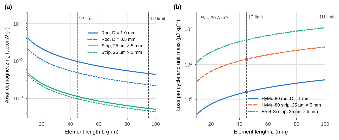
(a) Axial demagnetizing factor of cylindrical rods (Eq. (5)) and of 25 µm strips (Aharoni’s exact prism solution [49]) versus length; dashed lines mark the longest elements that fit a 1P and a 1U unit. (b) Hysteresis loss per cycle and per unit mass of damper material for A m⁻¹, from Eqs. (6) and (7) with A m⁻¹, T for HyMu-80 [12] and A m⁻¹, T for annealed Fe–B–Si [51, 52]; markers indicate the 1P limit.
5.3. Magnet-induced bias: the dominant 1P constraint#
Because the magnet moment does not scale down (Section 5.1), the dampers of a 1P unit sit in a much stronger stray field. The field magnitude of a dipole of moment is in its equatorial plane and twice that, , on its axis. For A m², this gives 0.19–1.0 kA m⁻¹ at the 20–35 mm distances available in a 1P unit, i.e. 5–60 times the geomagnetic field of 16–40 A m⁻¹ (20–50 µT) in LEO (Fig. 5a). A damper remains active only while the total axial field stays below its apparent saturation field,
which is 5.7 kA m⁻¹ for the 1 mm, 45 mm HyMu-80 rod, but only 1.4 kA m⁻¹ for the Fe–B–Si strip and 0.67 kA m⁻¹ for a HyMu-80 strip of the same size. With A m², the Fe–B–Si strip saturates within about 18 mm of the magnet in its equatorial plane and the HyMu-80 strip within about 23 mm—distances comparable to the half-width of the unit. The same applies to slender rods: for the 0.2 × 0.2 × 33.5 mm HyMu-80 rod geometry reported for Grizu-263A [46], Aharoni’s solution gives and kA m⁻¹, which a 0.1 A m² dipole exceeds within about 17 mm in its equatorial plane and 21 mm on its axis.
Eq. (10) exposes a design conflict specific to small spacecraft: the more slender an element, the more energy it dissipates per unit volume (Eq. (8)), but the less bias it tolerates. In a 1P unit, therefore has an optimum fixed by the local bias field, and a high saturation polarization is valuable precisely here—not for the reason usually given—because Fe-based amorphous alloys ( T) tolerate twice the bias of 80% Ni–Fe (–0.80 T) at equal . Flight experience confirms the hazard: on Delfi-C3, despin took about three months instead of the few hours predicted, largely because rods near the permanent magnet were saturated [53]. By symmetry, the dipole field in the magnet’s equatorial plane is parallel to the magnet axis, so dampers lying in that plane and perpendicular to the magnet see no axial bias component; positions along the magnet axis are the least efficient [53]. The layout rules for a 1P unit are therefore: size no larger than Eq. (4) requires; place dampers in or close to the equatorial plane of the magnet; choose such that exceeds the local axial field by a margin (e.g. a factor of two); and verify the integrated configuration by magnetic mapping.
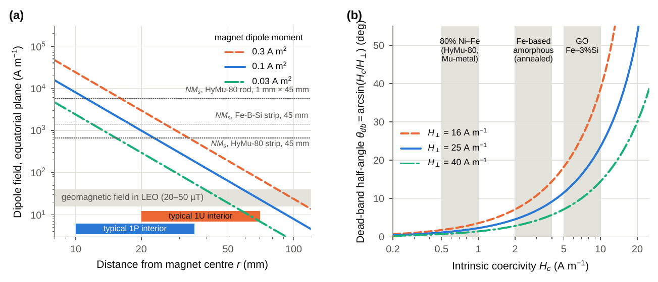
(a) Equatorial-plane field of permanent magnets of three dipole moments versus distance, compared with the geomagnetic field in LEO and with the apparent saturation fields (Eq. (10)) of 45 mm damper elements; bars indicate typical magnet-to-damper distances inside 1P and 1U units. (b) Dead-band half-angle below which hysteresis damping essentially vanishes (Eq. (11)), for three field magnitudes perpendicular to the magnet axis; shaded bands show typical coercivities of three alloy classes [50, 52].
5.4. Coercivity, dead band and hybrid damper sets#
Once the spacecraft has been despun, it librates about the field line. A damper perpendicular to the magnet then sees an axial field of amplitude , where is the geomagnetic field magnitude and the libration amplitude. Irreversible magnetization, and with it hysteresis loss, requires the applied field to exceed the coercivity; below that threshold only reversible Rayleigh-type losses remain, of the order of 4 × 10⁻³ of the maximum [53]. Hysteresis damping therefore effectively stops at a dead-band half-angle
which is 1.8° for HyMu-80 ( A m⁻¹), 5.7° for annealed Fe-based amorphous ribbon (≈3 A m⁻¹) and 10°–20° for grain-oriented Fe–3%Si (≈5–10 A m⁻¹) at A m⁻¹, and roughly twice as large at the weak-field end of LEO (Fig. 5b). Together with Eq. (7), in which the loss grows with , this defines a coercivity trade-off: high-coercivity dampers despin faster but leave a larger residual libration, whereas low-coercivity dampers keep damping down to small angles but dissipate less per cycle. Residual pointing accuracy in the field depends also on disturbance torques and on the rotation of the field along the orbit, so Eq. (11) gives a lower bound on the libration amplitude that hysteresis damping alone can reach, not a prediction of pointing error.
The trade-off is consistent with the simulations of Fiorillo et al., in which Fe-based amorphous strips gave the largest losses in both the oscillation (5 A m⁻¹) and spin (20 A m⁻¹) regimes, Fe–Si was comparable in spin, and mumetal was always inferior; their optimum array for 200 mm strips consisted of 20 µm thick, 5 mm wide amorphous ribbons separated by 10 mm gaps to limit mutual demagnetization [50]. For a 1P unit, these considerations suggest a hybrid damper set: Fe-based amorphous strips for fast despin and high bias tolerance, complemented by a few low-coercivity Ni–Fe elements that extend damping towards small libration angles, all mounted in the equatorial plane of the magnet and spaced to avoid mutual demagnetization. This recommendation follows from the first-order model above and still requires experimental confirmation (Section 9).
5.5. Metallurgy and processing of soft-magnetic dampers#
Table 4 summarizes the candidate alloys. The 80% Ni–Fe permalloys (Mu-metal, nominally 77Ni–16Fe–5Cu–2Cr by mass, and HyMu-80, 80Ni–4.2Mo–Fe) owe their very low coercivity to the simultaneous near-cancellation of the magnetocrystalline anisotropy constant and the magnetostriction close to this composition, assisted by Mo or Cu additions [54, 55]. Their properties are developed only by a final high-temperature anneal in dry hydrogen, which removes interstitial impurities (C, S, O) and coarsens the grains; any subsequent cold work—bending, cutting, machining, even rough handling—reintroduces dislocations and stress-induced anisotropy and can multiply the coercivity [54, 55]. Flight elements must therefore be annealed in their final shape and mounted without stress; UNISAT-3 experience showed that damper strips must be designed and manufactured with particular care, because their effective in-orbit magnetization is difficult to predict [14].
Fe-based amorphous ribbons are produced by planar-flow casting at cooling rates of about 10⁵ to 10⁶ K s⁻¹, a route that descends from the first metallic glasses [55, 56]. Metalloids (B, Si) stabilize the glassy state, and the absence of long-range order removes magnetocrystalline anisotropy, but the large saturation magnetostriction (27 × 10⁻⁶ for Metglas 2605SA1 [51]) makes the material sensitive to stress through the magnetoelastic anisotropy . A residual stress of only 10 MPa gives kJ m⁻³. If a ribbon ( ppm K⁻¹, GPa [51]) is rigidly bonded to FR-4 or aluminium, a 60 K excursion generates thermal stresses of about 50 MPa or 105 MPa, respectively, i.e. –4 kJ m⁻³—comparable to or larger than the weak uniaxial anisotropies that annealing induces in these alloys [52]. Amorphous dampers should therefore be field-annealed below the crystallization temperature (510 °C for 2605SA1 [51]), as in the strips characterized by Fiorillo et al. [50], then mounted so that they are free to expand (sleeves, channels, single-point tacking or compliant silicone). Annealed ribbons are brittle, which calls for controlled handling during integration. Co-based amorphous alloys avoid the stress sensitivity but have half the saturation polarization of 80% Ni–Fe and correspondingly poor bias tolerance. Nanocrystalline Fe–Cu–Nb–Si–B alloys [52, 57] combine near-zero magnetostriction with T and are, on paper, attractive for 1P dampers, but no flight heritage in PMAC is known to the author. All candidates have Curie temperatures well above PocketQube operating temperatures.
Table 4.Typical properties of soft-magnetic damper materials [50–52, 54, 55].
| Class (example) | Structure | (T) | (A m⁻¹) | (10⁻⁶) | (°C) | (g cm⁻³) | Processing and use notes |
|---|---|---|---|---|---|---|---|
| 80% Ni–Fe (HyMu-80, Mu-metal) | fcc, H₂-annealed | 0.74–0.80 | 0.5–1.0 | ≈0 | 400–460 | 8.7 | Lowest ; very sensitive to cold work; anneal in final shape |
| 50% Ni–Fe (Permenorm 5000 H2) | fcc | 1.50–1.55 | 2–8 | ≈25 | ≈470 | 8.25 | Higher and |
| Grain-oriented Fe–3%Si | bcc, Goss texture | 2.0 | 5–10ᵃ | ≈23ᵇ | ≈745 | 7.65 | Highest ; anisotropic; large dead band |
| Fe-based amorphous (Metglas 2605SA1) | amorphous ribbon, 25 µm | 1.56 | 2–4ᶜ | 27 | 395 | 7.18 | = 510 °C; field-annealed; stress-sensitive; brittle after annealing |
| Co-based amorphous | amorphous ribbon | 0.5–0.6 | 0.3–1 | ≈0 | 200–250 | ≈7.6 | Stress-insensitive; low bias tolerance |
| Nanocrystalline Fe–Cu–Nb–Si–B | bcc grains in amorphous matrix | 1.20–1.24 | 0.5–1.5 | ≈2 | ≈570 | 7.3 | Low , moderate ; brittle; no PMAC flight data known |
ᵃ Along the rolling direction. ᵇ . ᶜ After stress-relief or field annealing; as-cast values are higher.
5.6. Active alternatives and magnetic cleanliness#
Magnetorquers are the only practical actuators for active detumbling and momentum management in PocketQubes [8]. Delfi-PQ uses three custom magnetorquers and was designed to detumble from rates of up to 180° s⁻¹ [8, 58], and coils embedded as copper traces in multilayer PCBs have been proposed for magnetorquer-only control of a 1P unit [59]. For embedded coils the materials questions shift to copper: its resistivity rises by about 0.39% per kelvin, so the current and dipole delivered at fixed voltage vary by more than 10% over the eclipse swings of Section 6. Whatever the actuator, the dampers and magnetometers of a 50 mm cube share the volume with ferromagnetic parts—nickel underplating, Kovar leads, steel fasteners, battery cans—and with current loops that add to the residual dipole. The PocketQube Standard Issue 1 contains no magnetic-cleanliness requirement [3]; non-magnetic fasteners (titanium, A286 or brass) and a measured residual dipole are advisable for any PMAC design.
6. Thermal cycling, electronic packaging and solder metallurgy#
6.1. Thermal capacitance and orbital temperature swings#
The scale effect on thermal behaviour is captured by a single-node energy balance for a tumbling spacecraft of heat capacity and external area :
where is 1 in sunlight and 0 in eclipse, and are the absorptance and emittance, the solar constant, the albedo, the outgoing long-wave flux of the Earth, the angle from the sub-solar point, the internal dissipation and the Stefan–Boltzmann constant. The factor 1/4 is the ratio of mean projected to total area of a randomly tumbling convex body, and is the orientation-averaged view factor to the Earth, equal to 0.305 at km and identical to the value used for SMOG-1 [32]. Eq. (12) was integrated to a periodic state for a 550 km orbit with (eclipse fraction 37.2%, period 95.5 min), with and a specific heat of 858 J kg⁻¹ K⁻¹, both taken from the SMOG-1 thermal model (171.5 J K⁻¹ for 200 g) [32], W m⁻², and W m⁻² [60], and an internal dissipation proportional to area (0.25 W for 1P, 1.0 W for 1U). Appendix A lists all parameters.
The 1P unit at its mass limit cycles between −10.8 °C and 19.5 °C (ΔT = 30.3 K), with cooling rates up to 1.15 K min⁻¹; at the 200 g of SMOG-1, the swing grows to 36.8 K and 1.50 K min⁻¹. The corresponding 1U values are 23.4 K for 1.33 kg and 15.8 K for 2.00 kg (Fig. 6a). These are bulk values. External panels and poorly coupled components swing considerably more: Delfi-PQ recorded swings of up to 75 °C [7], and the finite-element model of SMOG-1 predicted extremes of about 15 °C and −26 °C, with the battery falling below 0 °C in eclipse in the conservative thermal-network model, so that charging had to be restricted to about half of the sunlit period [32]. Delfi-PQ was qualified by thermal-vacuum cycling between −20 °C and 50 °C [58], and PocketQubes have themselves served as materials test beds: the 2P ATL-1, launched on 6 December 2019, carried an in-orbit experiment on a new thermal-insulation material [61]. Four materials consequences follow: about 5500 eclipse cycles per year of operation; charging of Li-ion cells near or below 0 °C, which promotes lithium plating and must be inhibited or heated; possible freezing of water-based propellants (Section 8); and the thermal drift of permanent magnets and copper coils discussed in Section 5.
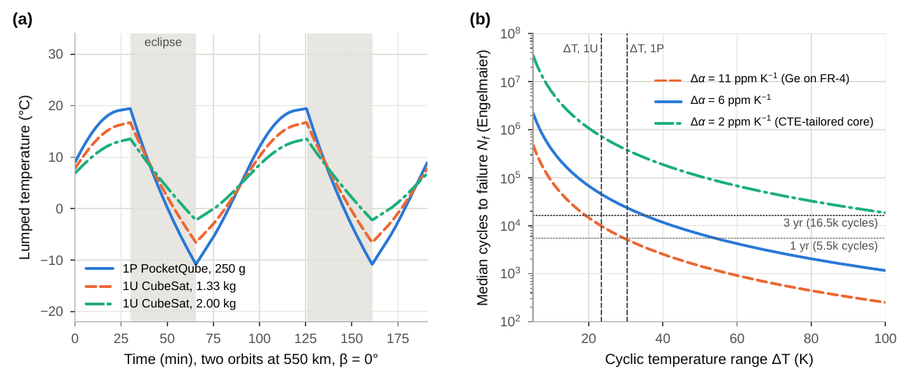
(a) Lumped temperature over two orbits from Eq. (12) for a 1P PocketQube at its mass limit and for 1U CubeSats of 1.33 kg and 2.00 kg. (b) Median cycles to failure of a rigid leadless solder joint from the Engelmaier model, Eqs. (13)–(14) ( mm, mm), for three expansion mismatches; the dashed verticals mark the swings of panel (a), and the dotted lines the number of eclipse cycles in one and three years.
Table 5.Typical linear expansion coefficients (near room temperature) of materials meeting in PocketQube assemblies.
| Material | (10⁻⁶ K⁻¹) | Role and remarks |
|---|---|---|
| Silicon | 2.6 | Dies; silicon solar cells |
| Germanium | 5.9 | Substrate of triple-junction solar cells |
| Alumina (96%) | 6.5–7.0 | Ceramic chip resistors and capacitors |
| Fe-based amorphous ribbon (2605SA1) | 7.6 | Hysteresis dampers [51] |
| Ti-6Al-4V | 8.6 | Inserts, fasteners |
| FR-4, in plane / out of plane () | 14–17 / 50–70 | PCBs and PCB-based structure; ≈ 130–180 °C |
| Carbon-core laminate, in plane | tunable, below FR-4 | Core thickness selected to approach the substrate [62] |
| Copper | 17 | Traces, planes, embedded coils |
| Sn–Ag–Cu (SAC305) | ≈22 | Lead-free solder |
| Al 6061-T6 | 23.6 | Structure, backplate |
| Sn63Pb37 | ≈24–25 | Space-grade eutectic solder |
| Space-grade silicone adhesives | ∼200–300 | Compliant bonding of cells and components |
Sources: [25, 28, 51, 62].
6.2. Expansion mismatch and solder-joint fatigue#
Table 5 lists the expansion coefficients that meet at PocketQube electronic assemblies. Body-mounted triple-junction solar cells are grown on germanium (α ≈ 5.9 ppm K⁻¹), whereas FR-4 expands by 14–17 ppm K⁻¹ in plane. Torabi et al. identified this mismatch as a risk of cracked cells and failed solder joints on body-mounted arrays of small spacecraft and proposed carbon-core laminates whose core thickness can be chosen to approach the expansion of the cell substrate [62]. For SwampSat, a PCB-based panel with soldered cells was preferred over a carbon-fibre composite panel with silicone-bonded cells for its reliability and compact packaging, and showed a mass loss of at most 0.024% after 19 h at 7.8 × 10⁻⁷ Torr [63].
To link the thermal swing to joint life, the Engelmaier model for rigid leadless surface-mount joints was used as a screening tool [64, 65]:
where is the median number of cycles to failure, the cyclic shear strain range, the fatigue ductility coefficient of eutectic Sn–Pb, an empirical factor, the distance from the neutral point, the joint height, the mean joint temperature in degrees Celsius and the number of cycles per day. With mm, mm, °C and per day, the 1P swing of 30.3 K gives cycles for ppm K⁻¹ (germanium on FR-4), i.e. about 0.9 years, against 2.4 × 10⁴ for 6 ppm K⁻¹ and 3.8 × 10⁵ for a CTE-tailored substrate with 2 ppm K⁻¹ (Fig. 6b). At the 36.8 K swing of a 200 g unit the FR-4 case falls to 3.1 × 10³ cycles (0.6 years), whereas the 1.33 kg 1U case reaches 9.9 × 10³ cycles (1.8 years).
These are median lives for idealized rigid joints in Sn–Pb solder; early failures occur well before , external panels experience larger swings than the lumped node, and creep and dwell effects are treated only implicitly. The screening nevertheless shows that the combination of low thermal capacitance and FR-4/germanium mismatch places rigidly soldered large components in a regime where joint life is commensurate with mission duration. Mitigations include CTE-tailored substrates [62], compliant attachment (silicone bonding with flexible interconnects instead of large rigid solder areas), smaller distances from the neutral point (smaller cells or split pads) and qualification by thermal cycling over the predicted range with margin. The out-of-plane expansion of FR-4, several times its in-plane value below and much larger above it, also fatigues plated through-holes, which favours high- laminates for boards that also carry structural loads.
6.3. Solder and surface-finish metallurgy#
High-reliability space soldering standards are built around eutectic and near-eutectic Sn–Pb alloys [66], whereas PocketQubes rely heavily on commercial parts with lead-free finishes [8]. Three metallurgical failure modes deserve attention. Tin whiskers are filamentary single crystals that grow spontaneously from tin-rich finishes under compressive stress, generated mainly by the growth of Cu₆Sn₅ intermetallic at the tin–copper interface and by expansion mismatch; vacuum does not cause them, but in vacuum a whisker short can sustain a metal-vapour arc, and detached whiskers become conductive debris [67, 68]. NASA and military parts specifications therefore prohibit pure-tin finishes, typically requiring at least 3% lead [69]; for commercial parts, mitigation relies on re-tinning with Sn–Pb solder, conformal coating and avoidance of bright tin over copper. Tin pest, the allotropic transformation of β-Sn into brittle α-Sn below 13.2 °C, is very slow, is inhibited by lead, bismuth and antimony, and is a concern only for long durations at low temperature [70]—but cold-biased PocketQube interiors (Fig. 6a) and lead-free assemblies make it worth noting. Finally, gold dissolving from thick gold finishes forms brittle AuSn₄ in the joint, which is why space soldering standards require de-golding of gold-plated terminations [66]. Flux residues, besides their corrosive potential, are an outgassing source and should be removed and verified by cleanliness testing (Section 7).
7. Polymers, additive manufacturing and molecular contamination#
7.1. Outgassing screening and its interpretation#
Polymers, adhesives, laminates, flux residues and composite matrices release absorbed water, solvents and low-molecular-weight species in vacuum. Condensable fractions collect on cold surfaces—optics, solar cells, thermal-control surfaces—and, in a shared deployer, also on neighbouring spacecraft; an AlbaPod v2 carries up to six PocketQube units [33], Delfi-PQ flew a laser-reflector payload whose performance depends on clean optical surfaces [7], and the 1P POQUITO, launched in January 2025, demonstrates an LED-based optical link to a ChipSat payload [71]. ECSS-Q-ST-70-02C screens materials by heating them to 125 °C for 24 h at no more than 1 × 10⁻³ Pa with a collector at 25 °C, and accepts them when the recovered mass loss (RML, the total mass loss TML minus the water vapour regained, WVR) is below 1.0% and the collected volatile condensable material (CVCM) is below 0.10% [11]. ASTM E595 applies the same thresholds to TML instead of RML [72]. PQ-Gen-04 states TML and CVCM limits but cites the ECSS document [3]. Because TML ≥ RML, the PocketQube clause is the more conservative reading, but it can reject hygroscopic materials, such as polyimide film with a TML of 0.97% of which 0.80% is water [73, 74], that ECSS would accept. A future revision would benefit from stating which parameter governs. ECSS-Q-ST-70-02C also notes that the 125 °C screening is suitable for materials operating below 50 °C and that materials expected to exceed 50 °C for extended periods need further testing [11]; given the swings recorded on Delfi-PQ [7], this applies to external PocketQube panels. Vacuum bake-out of the integrated spacecraft, performed for Delfi-PQ at 50 °C and 1 × 10⁻⁵ mbar for 24 h [58], removes much of the residual water and solvent.
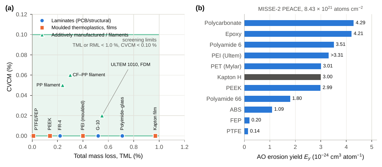
(a) Outgassing screening data (TML versus CVCM) for laminates, moulded thermoplastics and additively manufactured or filament materials relevant to PocketQubes [73, 75, 76]; the shaded region marks the screening limits. Materials with CVCM of zero are labelled vertically. (b) Atomic-oxygen erosion yields measured on the MISSE-2 PEACE experiment, with Kapton H as the reference material; “>” indicates a lower bound [77, 78].
7.2. Additively manufactured polymers and composites#
AM polymers enter PocketQubes and their deployers as structures, brackets, antenna housings and mechanisms (Table 6, Fig. 7a). The laser-sintered, carbon-filled polyamide Windform XT 2.0 passed ESA micro-VCM screening in both coated and uncoated form [79] and forms the shell, ejection mechanism and door of the AlbaPod v2 deployer, which weighs less than 500 g, about 60% less than its predecessor [33]; by 2024 AlbaPod v2 had completed eight missions deploying 41 PocketQubes [5]. Fused-filament (FDM) PEEK has reached TRL 7 in a 1U structure with a TML of 0.11% [5], and FDM ULTEM 1010 passes the screening limits in both build orientations [75]. The RedPill 2P PocketQube illustrates the practical trade-offs: its antenna winding is printed in PET, chosen over PEEK because it can be printed in-house, while steel measuring tape was rejected for the antenna elements in favour of uncoated stainless spring steel because of outgassing and atomic-oxygen concerns [80].
Two properties of printed polymers are easily overlooked. First, they are anisotropic: FDM ULTEM 9085 loses about 40% of its tensile strength between the in-plane (XZ, 69 MPa) and the build (ZX, 42 MPa) directions [31], so that the orientation of a printed part must be recorded together with its outgassing data. Second, the porosity and surface area of printed parts favour moisture uptake, which inflates TML and WVR and makes bake-out particularly effective. Commodity prototyping polymers such as ABS and PLA have outgassing behaviour that depends strongly on grade and additives and, in the case of PLA, a low glass-transition temperature; they are suitable for engineering models but should be replaced or qualified individually for flight.
External polymer surfaces also face atomic oxygen (AO). The recession depth of a surface is , where is the erosion yield and the fluence. MISSE-2 accumulated atoms cm⁻² in 3.95 years in ram orientation on the International Space Station [77], i.e. about 2 × 10²¹ atoms cm⁻² per year; for PEEK ( cm³ per atom) this corresponds to a recession of about 60 µm per year. A randomly tumbling cube exposes each face to roughly one quarter of the ram fluence, and fluences at 500–550 km are substantially lower and depend on solar activity. Fluoropolymers erode 15–21 times more slowly than polyimide (Fig. 7b) but creep under load, whereas ABS, with about one third of that of Kapton, is comparatively AO-resistant although its outgassing is grade-dependent.
Table 6.Outgassing screening data and atomic-oxygen erosion yields of polymers relevant to PocketQubes.
| Material | TML (%) | CVCM (%) | WVR (%) | (10⁻²⁴ cm³ atom⁻¹) | Remarks |
|---|---|---|---|---|---|
| FR-4 laminate | 0.22 | 0.00 | 0.09 | – | PCBs, PCB-based structure; epoxy matrix = 4.21 |
| G-10 laminate | 0.52 | 0.00 | 0.16 | – | Structural glass–epoxy |
| Polyimide–glass laminate | 0.71 | 0.00 | 0.40 | – | High- PCBs |
| PEEK, moulded | 0.14 | 0.00 | 0.05 | 2.99 | Low outgassing; high-temperature capable |
| PEEK, FDM structure (AMCUBE) | 0.11 | n.r. | n.r. | – | 96 g 1U structure, TRL 7 [5] |
| PEI (Ultem), moulded | 0.40 | 0.00 | 0.32 | >3.31 | |
| ULTEM 1010, FDM (XY / ZX) | 0.55 / 0.58 | 0.02 / 0.03 | 0.39 / 0.33 | – | As-printed material [75] |
| Polypropylene filament (unfilled / CF) | 0.24 / 0.30 | 0.05 / 0.06 | 0.03 / 0.03 | – | FDM filaments [76] |
| Windform XT 2.0, SLS | passed ESA µVCM screening | – | Values not published [79]; polyamide matrix | ||
| Polyimide film (Kapton) | 0.97 | 0.00 | 0.80 | 3.00 | Reference for ; mostly water |
| PET film (Mylar) | 0.24 | 0.01 | 0.18 | 3.01 | PET also used in FDM form [80] |
| PTFE / FEP | 0.01 | 0.00 | 0.02 | 0.142 / 0.200 | Lowest AO erosion; creep |
| ABS | grade-dependent | 1.09 | Common prototyping polymer | ||
| Polyamide 6 / 66 | grade-dependent | 3.51 / 1.80 |
Outgassing data from the NASA outgassing database unless noted [73, 74]; erosion yields from MISSE-2 PEACE [77, 78]. n.r. = not reported.
7.3. Additively manufactured metals#
For metallic AM parts, the issues are surface rather than bulk: LPBF AlSi10Mg matches 6061-T6 in yield strength (Table 2), but its as-built roughness and Si network degrade hard-anodic films [40], which matters wherever PQ-Mat-03 applies. Valencia et al. concluded that AA6061-T6 remains the de facto PocketQube structural alloy, that topology-optimized AM designs could save 30–60% of structural mass, and that dedicated qualification pathways and in-orbit validation of metallic AM structures are still lacking [5].
8. Propulsion and energy-storage materials#
Propulsion is regarded as the key enabling technology for future PocketQube missions [1], and MEMS-fabricated systems are the main route to fitting thrusters into the available volume [15]. Delft University of Technology developed two water-based micro-resistojet concepts—a vaporizing-liquid microthruster and a low-pressure microthruster—as green options for very small spacecraft [81], and allocated a propulsion payload with a wet mass below 75 g, a peak power of 4 W and an envelope of 42 × 42 × 30 mm to Delfi-PQ, combining both technologies on one PCB [58]. The materials issues of such systems arise at interfaces: silicon chips with integrated thin-film heaters must survive repeated heating from the cold eclipse conditions of Section 6, which loads the heater films and their adhesion layers in thermal fatigue; wetted metals and seals must be compatible with water and, for elastomers, with the outgassing limits of PQ-Gen-04; and the lumped temperature of a 1P unit falls below 0 °C in eclipse (Fig. 6a), so that water feed systems require thermal isolation or heater power to avoid freezing.
Energy storage is constrained by PQ-Gen-03, which exempts Li-ion cells from the prohibition of hazardous materials only if thermal runaway is adequately prevented; launch providers may require additional tests [3]. Battery protection limitations were among the lessons of Delfi-PQ [7], and the battery was the temperature-limiting component of SMOG-1 [32]. Three materials-related measures follow from the preceding sections: inhibit charging near or below 0 °C, where lithium plating on graphite anodes becomes likely; restrain pouch-format cells mechanically, since they can swell when internal gas evolves in vacuum; and include the cell, its separator and its electrolyte in the outgassing and venting assessment of the spacecraft.
9. Integrated design guide, verification and research gaps#
9.1. Design and verification matrix#
Table 7 condenses the preceding sections into recommendations that can be applied at the preliminary design review of a PocketQube and verified before delivery to the launch service. Two cross-cutting principles emerge. First, the interfaces of a PocketQube—the backplate clamps, the contact faces, the mounts of magnetic elements and the solder joints—are more critical than its bulk materials, because scaling has reduced bulk loads but not interface sensitivities. Second, several CubeSat heuristics change sign at 1P scale: rod length matters less than expected for despin but magnet bias matters more; saturation polarization matters for bias tolerance rather than for energy dissipation; and a lighter spacecraft cycles thermally harder.
Table 7.Materials design and verification matrix for PocketQubes.
| Item | PocketQube-specific risk | Recommended materials and processes | Verification |
|---|---|---|---|
| Backplate and contact faces | SCC of peak-aged 7xxx; tolerance consumed by coating growth; fretting and cold welding in the deployer | 6061-T6 or 6082-T6 (or 7075-T73/T7351); Type III film of 25–50 µm specified on drawing; machine undersize by growth; edge radii; Ra < 1.6 µm | SCEF where required; film thickness and dimensions after coating; vibration followed by vacuum dwell and ejection/separation test |
| Primary structure | Mass budget; PCB-as-structure couples thermal and electrical design | Al 6061-T6 frames or FR-4/high- laminates as panels; Mg only with LSP consent | Sine and random vibration; resonance search; inspection of bonded and threaded joints |
| Fasteners, inserts, hinges | Galling and cold welding of like metals; fatigue of anodized parts | Dissimilar or coated pairs (e.g. Ti or A286 against anodized Al); no hard anodizing on cyclically stressed parts without fatigue margin | Torque–tension and run-down tests; thermal-vacuum cycling |
| Permanent magnet | Thermal drift of moment; demagnetization of short AlNiCo; bias of dampers | AlNiCo 5 in elongated form or SmCo; NdFeB only in high-temperature grades; smallest m satisfying Eq. (4) | Magnetic moment at temperature extremes; stray-field map of the integrated unit |
| Hysteresis dampers | Demagnetization, magnet bias, coercivity dead band, stress sensitivity | Hybrid set of field-annealed Fe-based amorphous strips and H₂-annealed 80% Ni–Fe; elements in the magnet’s equatorial plane; ; stress-free mounting | B–H loops of flight elements after integration; air-bearing or Helmholtz-cage damping test |
| Electronics and solar panels | Large eclipse swings; FR-4/Ge and FR-4/ceramic CTE mismatch | CTE-tailored cores or compliant silicone attachment; small ; Sn–Pb solder or re-tinned terminations; conformal coating | Thermal cycling over the predicted range with margin; X-ray and cross-sections of joints |
| Polymers and AM parts | Outgassing near optics and shared deployers; AO erosion; anisotropy | PEEK, PEI, Windform XT 2.0 or other materials with measured data in the printed state; record build orientation; avoid commodity PLA for flight | ECSS-Q-ST-70-02C screening of the as-built material (and at > 50 °C where relevant); vacuum bake-out |
| Batteries and propulsion | Thermal runaway; lithium plating in the cold; swelling; propellant freezing | Protected Li-ion cells; charge inhibit or heating near 0 °C; mechanical restraint of pouches; thermal isolation of water systems | LSP-specified battery tests; thermal-vacuum test at the cold case |
| Magnetic cleanliness | Residual dipole dominates disturbance torques of a 1P unit | Non-magnetic fasteners; avoid Ni-plated and Kovar parts near dampers; minimize current-loop areas | Residual-dipole measurement of the integrated unit |
9.2. Research gaps#
The analysis also exposes where evidence is missing. In order of their estimated impact on mission success, the following gaps are proposed for future work:
- Vacuum fretting and separation data for PocketQube interfaces. No open data were found on the adhesion of hard-anodized aluminium, or of FR-4, against deployer-rail materials after vibration and vacuum dwell. A test campaign following ESA STM-279 [35] on representative backplate–rail pairs would close this gap.
- Bias-aware design and in-orbit validation of 1P dampers. The demagnetization and bias analysis of Section 5 should be validated by laboratory measurements of complete magnet–damper layouts and, ultimately, by flight telemetry of rates and libration amplitudes.
- Magnetic cleanliness in the PocketQube Standard. Because residual dipoles dominate 1P disturbance torques, a recommended limit or a measurement requirement would benefit all PMAC missions.
- Thermal-cycling reliability of PocketQube-scale assemblies. Joint-level data for body-mounted cells on FR-4 and on CTE-tailored laminates under 30–40 K eclipse cycles are needed to replace screening models such as Eq. (13).
- Outgassing of printed materials above 50 °C. Published data for AM polymers rarely state build orientation, post-processing or test temperature, although all three affect the result.
- Qualification of small AM parts. A de-rated qualification pathway for parts below 100 g is absent from current standards [5].
- Clarification of PQ-Mat-02 and PQ-Gen-04. Specifying tempers for the recommended alloys and the governing outgassing parameter (TML or RML) would align the PocketQube Standard with the ECSS documents it cites.
10. Conclusions#
This review has examined the materials engineering of PocketQube picosatellites through the lens of scaling, testing inherited CubeSat practice and the material clauses of the PocketQube Standard against the physics that governs them at 1P size. The main conclusions are as follows.
- Halving the cube edge reduces the principal moment of inertia to 3.1–4.7% of that of a 1U CubeSat and the thermal inertia per unit area to 50–75%, raises aerodynamic angular accelerations by a factor of 2.7–4, leaves gravity-gradient angular accelerations unchanged and increases the stray field of a fixed-moment magnet at the inner walls eightfold. These ratios, not the volume ratio of 1/8, determine which materials practices transfer.
- The 1.6 mm sliding backplate is interface-critical rather than strength-critical: bearing pressures are of the order of 0.2 MPa, whereas tolerance, coating growth and fretting behaviour govern performance. Because ECSS-Q-ST-70-36C classes 7075-T6 as having low SCC resistance, the unspecified “7075” of PQ-Mat-02 should be read as 7075-T73/T7351 (or T76 under the thin-sheet exemption); 6061-T6 and 6082-T6 meet the interface requirements with high SCC resistance.
- Hard anodizing mitigates cold welding by replacing metal-to-metal contact, but a 50 µm film consumes half of the backplate width tolerance, reduces the fatigue strength of 6082 by 50–62% and performs worse on high-silicon AM alloys. Coating type, thickness and sealing should be specified and verified, and vacuum fretting data for PocketQube interfaces are still missing.
- Soft-magnetic dampers in a 1P unit operate in a demagnetization-limited regime in which saturation polarization does not limit energy dissipation. The shorter elements reduce dissipation per element (), but the much smaller inertia more than compensates, so despin times of the same rod complement are about five times shorter than in a 1U CubeSat. The constraints that dominate instead are the bias imposed by the permanent magnet, which saturates slender elements within about 17–23 mm of a 0.1 A m² dipole, and the coercivity dead band of about 2° for 80% Ni–Fe and 6° for annealed Fe-based amorphous ribbons.
- High saturation polarization is valuable because it raises the bias tolerance , not because it enlarges the loop. Hybrid damper sets of stress-free, field-annealed Fe-based amorphous strips and low-coercivity Ni–Fe elements placed in the magnet’s equatorial plane are therefore proposed for 1P PMAC, together with thermally stable AlNiCo 5 or SmCo magnets sized no larger than the disturbance torques require.
- A lumped orbital model predicts eclipse swings of 30–37 K for 1P units, against 16–23 K for 1U CubeSats. Combined with the FR-4/germanium expansion mismatch, an Engelmaier screening gives median lives of rigid solder joints of about one year, which makes CTE-tailored substrates or compliant attachment necessary for long missions.
- The outgassing clause PQ-Gen-04 applies a TML criterion while citing a standard that screens on RML; laminates, PEEK, PEI and the printed materials with published data pass the screening limits, but test temperature, build orientation and moisture state must be reported for printed parts, and external parts above 50 °C require further characterization.
The models used here are first-order and should be refined by testing. Their value lies in showing that the miniaturization from CubeSat to PocketQube does not merely shrink materials problems; it reorders them.
Declarations#
Competing interest. nadir lab. declares no known competing financial interests or personal relationships that could have appeared to influence the work reported in this paper.
Data availability. All data used in this review are taken from the cited sources. The scripts that reproduce the figures and the analytical results of Sections 2, 5 and 6 will be made available as supplementary material.
Use of generative AI. During the preparation of this work for exclusive publication on nadir lab., generative AI tools (Claude, Anthropic) were used to assist with literature structuring, language editing, and preparing the first-order analytical calculations and figures. The content was reviewed, verified, and edited as needed, and nadir lab. takes full responsibility for the content of the publication.
Appendix A. Model inputs#
Table A.1 lists the inputs of the first-order models used in Sections 2, 5 and 6. Eq. (12) was integrated with a fourth-order Runge–Kutta scheme and a time step of 2 s over 14 orbits, of which the last two are shown in Fig. 6(a). Aharoni’s closed-form demagnetizing factor [49] was evaluated in 60-digit decimal arithmetic; the implementation reproduces for a cube, satisfies to machine precision and agrees with the rectangular-rod approximation of Sato and Ishii [48] to within 6% for square rods.
Table A.1.Inputs of the first-order models.
| Model | Inputs | Source |
|---|---|---|
| Scaling (Fig. 1) | L = 50 mm vs 100 mm; M = 250 g vs 1.33 kg; centre-of-mass tolerance 1 cm vs 2 cm; longest damper 45 mm vs 95 mm | [3, 9, 12] |
| Backplate (Fig. 3) | Solid 58 × 64 × 1.6 mm plate; ρ, E, ν of Table 2 | [3, 25, 28] |
| Magnet sizing (Eq. (4)) | = 10; = 20 µT; = 10°; = 2.2; v = 7.6 km s⁻¹; = (1–5) × 10⁻¹² kg m⁻³; residual dipole 1 × 10⁻³ A m² (assumed) | [12, 13] |
| Damping (Fig. 4) | = 30 A m⁻¹; HyMu-80: = 0.96 A m⁻¹, = 0.74 T, ρ = 8.7 g cm⁻³; Fe–B–Si: = 3 A m⁻¹, = 1.56 T, ρ = 7.18 g cm⁻³; idealized rectangular loop | [12, 51, 52] |
| Despin (Eq. (9)) | = 10° s⁻¹; = 0.6; four elements; homogeneous cube inertia (Eq. (1)) | [53] |
| Thermal (Eq. (12)) | h = 550 km, β = 0°; S = 1361 W m⁻²; a = 0.30; = 237 W m⁻²; α = ε = 0.85; = 858 J kg⁻¹ K⁻¹; A = 0.015 m² (1P), 0.06 m² (1U); = 0.25 W (1P), 1.0 W (1U) | [32, 60] |
| Solder fatigue (Eqs. (13)–(14)) | = 5 mm; h = 0.1 mm; = 1; = 0.325; = 5 °C; f = 15.1 d⁻¹ | [64, 65] |