Non-pyrotechnic antenna deployment in PocketQube-class satellites: strain and thermal budgets for NiTi tapes and release actuators
- Research group
- nadir lab.
- Published
- 22 October 2026
- Version
- nadir lab. Monograph REV 0.1, 22 October 2026
- Identifier
- SQ-R-003
- Reading time
- 34 min
- Licence
- CC BY-NC-ND 4.0
At a glance
- outer-fibre strain of a 0.10 mm tape wound on a 3 mm hub
- 1.67%
- higher deployment energy stored by superelastic NiTi than thin spring steel at −20 °C
- 5×
- of stored NiTi energy absorbed by 1 N of cold-welded adhesion over the stroke at −20 °C
- 87%
- heating energy at 1 W (0.23 s) for a 0.15 mm one-way NiTi release wire
- 0.23 J
Highlights
- Strain budget, not actuator energy, sets the feasible tape thickness at 1P
- A 0.10 mm superelastic NiTi tape fits a 3 mm hub; spring steel needs 0.036 mm
- At −20 °C, superelastic NiTi stores five times the deployment energy of thin steel
- At −20 °C, 1 N of cold-welded adhesion would absorb most of the stored energy
- A one-way NiTi release wire needs about 0.23 J at 1 W, under half a second
Abstract
Antenna deployment in PocketQubes must meet constraints that are unusual for larger spacecraft: no pyrotechnic devices, a 7 mm external envelope and a 250 g mass limit for 1P. This article compares two material routes for a tape-type antenna, spring steel and superelastic NiTi, and sizes a one-way NiTi release actuator, using first-order closed-form models. A tape of thickness t wound to a mid-surface radius R carries an outer-fibre strain t/2R. On a 3 mm hub, a 0.10 mm tape reaches 1.7 %. This exceeds the recoverable strain of spring steel (about 0.6 %) and beryllium copper (about 0.9 %), but lies within the superelastic plateau of NiTi (4 % design value). Spring steel must thin to 0.036 mm to stay elastic and then stores about 0.04 J over a 170 mm stroke, against about 0.20 J for NiTi at −20 °C and 0.42 J at 25 °C. A cold-welded adhesion of 1 N along the stroke would absorb about 40 % of the NiTi energy at 25 °C and about 87 % at −20 °C, where the plateau stress is lowest. Under a constant strain budget, halving the cube edge halves the admissible thickness, the stored energy per unit length and the restraint force. For release, a 0.15 mm one-way NiTi wire supplies about 5 N and needs about 0.23 J at 1 W. The wire’s transformation-start temperature must exceed the hottest operating temperature by a margin, while the superelastic tape’s finish temperature must lie below the coldest one. Restraint creep, latch mismatch and outgassing are treated, and a verification matrix is proposed.
- PocketQube
- Picosatellite
- Antenna deployment
- NiTi shape-memory alloy
- Superelasticity
- Strain budget
- Non-pyrotechnic release
- Cold welding
Abbreviations (13)
- CFRP
- Carbon-fibre-reinforced polymer
- CVCM
- Collected volatile condensable material
- DSC
- Differential scanning calorimetry
- ECSS
- European Cooperation for Space Standardization
- LCP
- Liquid-crystal polymer
- LEO
- Low Earth orbit
- NiTi
- Nickel–titanium (nitinol) shape-memory alloy
- RML
- Recovered mass loss
- SCC
- Stress-corrosion cracking
- SMA
- Shape-memory alloy
- TML
- Total mass loss
- UHMWPE
- Ultra-high-molecular-weight polyethylene
- WVR
- Water vapour regained
Contents
Full text
1. Introduction#
1.1. Antennas at 1P scale#
PocketQubes are 50 mm cubes with a mass of at most 250 g per unit [1, 2]. Their telemetry links commonly use VHF and UHF bands, and a quarter-wave element is 0.52 m long at 145 MHz and 0.17 m long at 437 MHz (values computed here). Both lengths exceed the cube, so the element must be stowed against the spacecraft and released after ejection. Deployable antennas are therefore a recurring feature of the platform. The 3P Delfi-PQ was designed with a deployable VHF/UHF system [3], and the 3P Delfi-Twin carries a 5 m dipole whose deployment design uses torsion-spring hinges and a burn-wire hold-down [4]. For the Delfi-Twin amateur-band antennas, TU Delft selected the shape-memory alloy nitinol and reported that its high electrical resistivity limits antenna efficiency [5].
1.2. Constraints of the PocketQube Standard#
The PocketQube Standard [1] sets several constraints that apply directly to a stowed element. Pyrotechnics are not allowed on board (PQ-Gen-02), and toxic or hazardous materials are excluded (PQ-Gen-03). Components must lie within a 7 mm envelope, and deployables may use up to 10 mm only with a waiver from the launch service provider (PQ-Mech-08). Deployables must be retained by the PocketQube rather than by the deployer (PQ-Mech-09). The recommended aluminium alloys are referenced to ECSS-Q-ST-70-36C for stress-corrosion cracking [23], and materials outside that list need consultation with the launch service provider (PQ-Mat-04). Outgassing must meet a total mass loss of 1.0 % or less and a collected volatile condensable material content of 0.1 % or less (PQ-Gen-04), with the test method referenced to ECSS-Q-ST-70-02C [1, 6].
1.3. Release and deployment options#
Three release families are used on small spacecraft. Burn wires cut a restraining filament by resistive heating [4]. Shape-memory actuators move when a NiTi element is heated through its transformation temperatures [10, 11]. Elastic elements such as spring steel, beryllium copper and tape springs store energy as strain while they are folded or coiled [18]. Superelastic NiTi is a special case in which large recoverable strains are carried by stress-induced martensite rather than by elastic deformation [10, 12]. Reviews of shape-memory applications in aerospace [14, 15] and of tape-spring deployment [18] cover the general case. For PocketQube-class elements, the designer must answer three questions together. How much strain can the stowed element carry without permanent set? How much deployment energy does it store, compared with the adhesion that cold welding can add in vacuum [8, 9]? Where must the transformation temperatures lie relative to the thermal range of the spacecraft [10, 16]? This article supplies one closed-form budget that answers all three.
1.4. Contributions and scope#
This article makes four contributions.
- It derives the outer-fibre strain of a coiled tape and screens six candidate materials against their recoverable strain (Sections 2 and 3).
- It compares the stored energy, restraint force and cold-welding margin of a spring-steel element and a superelastic NiTi element, and shows how these change when the cube edge is halved at constant strain (Sections 4 and 5).
- It places the transformation windows of two NiTi compositions against the operating range and sizes a one-way NiTi release actuator (Sections 6 and 7).
- It collects restraint, latch and thermal-mismatch issues and gives a verification matrix (Sections 8 and 9).
The models are first order. The reference element is 170 mm long, the operating range is −20 °C to +50 °C and the coil hub radius is 3 mm unless stated otherwise. Material values are representative and are listed with their sources or assumptions in Appendix A; they must be replaced by qualified data before design. The analysis covers 1P units in low Earth orbit.
2. Requirements and stowage geometry#
The design is bounded by the requirements in Table 1. Most of them are fixed by the PocketQube Standard. The operating range and stowage time are design assumptions that the verification plan in Section 9 must cover.
Table 1.Requirements that bear on a stowed antenna element.
| Requirement | Value used here | Basis |
|---|---|---|
| Components envelope | Within 7 mm of the cube face | PQ-Mech-08 [1] |
| Deployables envelope | Up to 10 mm, only with a launch-provider waiver | PQ-Mech-08 [1] |
| Release | No pyrotechnic devices | PQ-Gen-02 [1] |
| Materials | No toxic or hazardous materials; other materials need launch-provider consultation | PQ-Gen-03; PQ-Mat-04 [1] |
| Retention | Deployables held by the PocketQube, not by the deployer | PQ-Mech-09 [1] |
| Outgassing | TML ≤ 1.0 %, CVCM ≤ 0.1 % | PQ-Gen-04 [1]; ECSS-Q-ST-70-02C [6]; ASTM E595 [7] |
| Mass | ≤ 250 g for the whole 1P unit | PQ-Mass-01 [1] |
| Operating range | −20 °C to +50 °C | Design assumption |
| Stowage time | Months between integration and ejection | Design assumption |
| Cold welding | Metal contacts sliding in vacuum | ESA STM-279 [8]; Roberts [9] |
2.1. Coil geometry and envelope#
The reference element is a tape of width and length , the quarter-wave length at 437 MHz. It is stowed as a spiral whose axis is normal to the cube face, so the tape width is the stack height. A 6 mm stack lies inside the 7 mm component envelope and therefore needs no waiver. The coil lies flat on the face, and its footprint is set by the hub radius and the number of wraps.
Wrap has mid-surface radius , where is the hub radius and the tape thickness, and its length is . The wrap count for a given element length satisfies
With the baseline hub radius , a 0.10 mm tape needs wraps for 170 mm, and the coil has an outer diameter of 7.6 mm. A 0.036 mm strip needs about 8.5 wraps and has an outer diameter of 6.6 mm. Both coils fit on the cube face and leave room for a latch. Because the hub and latch must be carried by the PocketQube (PQ-Mech-09), the whole release system sits on the spacecraft and not on the deployer.
The restraint force at the hub is approximated as , where is the bending moment of the innermost wrap. This first-order estimate sets the load that the latch must hold until release.
3. Strain budget of coiled tapes#
The first screen is the outer-fibre strain at the innermost wrap. On the 3 mm hub, only superelastic NiTi keeps a 0.10 mm tape within its recoverable strain.
Under pure bending the strain varies linearly through the thickness and is largest at the outer surface. With the mid-surface radius, that strain is . The tape can be coiled without permanent set only while stays below the recoverable strain , so the thickest admissible tape on a given hub is .
Table 2.Recoverable strain of candidate materials. Values are representative and are listed in Appendix A.
| Material and condition | Form | Recoverable strain (%) | Basis |
|---|---|---|---|
| Hardened stainless or high-carbon spring steel | Strip | 0.6 | Elastic limit; |
| 17-7PH, TH1050 | Strip | 0.6 | Elastic limit; |
| Ti-6Al-4V, annealed | Strip | 0.8 | Elastic limit; |
| Beryllium copper, heat-treated | Strip | 0.9 | Elastic limit; benchmark only, toxicity under PQ-Gen-03 |
| Unidirectional CFRP | Tape spring | 1.0 | Matrix-limited assumption |
| Superelastic NiTi, Ni-rich, aged | Strip | 4.0 | Design value; good material reaches 6 to 8 % [10, 15] |
At and the outer-fibre strain is 1.67 %. Only superelastic NiTi tolerates this strain with margin, a safety factor of 2.4 against its design value. The other five candidates would each need a tape 40 % to 65 % thinner than 0.10 mm, as Figure 1 shows.
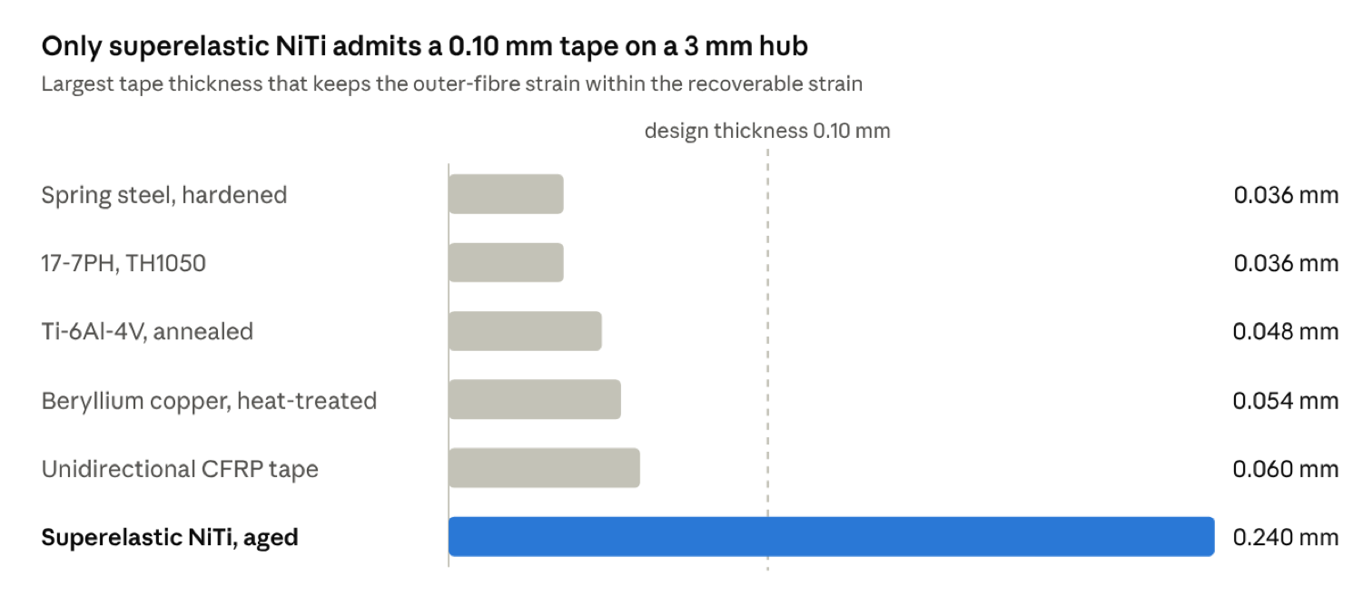
Largest admissible tape thickness on a 3 mm hub for the six candidate materials. Calculated as with ; inputs in Table 2 and Appendix A.
Thin tapes carry a stiffness penalty. The bending stiffness of a strip is , so a 0.036 mm steel strip is about 21 times less stiff than a 0.10 mm strip of the same width and material. Superelastic NiTi has an austenite modulus of roughly 60 to 80 GPa [10], which still leaves the 0.10 mm NiTi tape about 6 to 9 times stiffer than the thin steel. The thin steel is also more prone to buckling and to damage during handling.
Hub size is the other lever. The admissible thickness scales with the hub radius, so a larger hub relaxes the constraint. At the spring-steel limit rises to 0.048 mm and the NiTi safety factor rises to 3.2. Spring steel admits a 0.10 mm tape only on a hub of 8.3 mm radius, which gives a coil about 17 mm across for the 170 mm element and occupies a much larger part of the 50 mm face. These hub sizes trade strain against footprint and against stored energy, which Section 4 quantifies.
4. Stored energy, restraint force and cold welding#
Deployment must pay for the energy that friction and cold welding absorb, so the stored energy is the budget that matters. The two elements differ in both magnitude and temperature dependence.
4.1. Moments and stored energy#
An elastic coil stores energy in proportion to the square of its curvature. With the second moment of area , the bending moment at the hub is , and the stored energy is the sum over all wraps. A superelastic strip behaves differently. Once its outer fibres enter the stress plateau, the moment stays close to a constant value, . This is an upper estimate, because the inner layers remain elastic. Each wrap then stores regardless of its radius, so the total for wraps is .
The plateau stress follows the Clausius–Clapeyron relation, , with [10, 11] and an assumed zero-stress martensite start for the Ni-rich aged alloy. This gives plateau stresses of about 260 MPa at −20 °C, 550 MPa at 25 °C and 715 MPa at 50 °C. Table 3 applies these expressions to the reference coil.
Table 3.Reference coil of 170 mm length on a 3 mm hub. Spring-steel properties use E = 200 GPa; the NiTi columns use the plateau stresses above.
| Quantity | Spring steel, | Superelastic NiTi, |
|---|---|---|
| Outer-fibre strain at the hub | 0.6 % | 1.67 % |
| Wraps for 170 mm | 8.6 | 8 |
| Bending moment at the hub | 1.6 mN·m | 3.9 mN·m at −20 °C; 10.7 mN·m at 50 °C |
| Restraint force at the hub, | 0.5 N | 1.3 N at −20 °C; 3.6 N at 50 °C |
| Stored energy at −20 °C | 0.04 J | 0.20 J |
| Stored energy at 25 °C | 0.04 J | 0.42 J |
| Stored energy at 50 °C | 0.04 J | 0.54 J |
| Adhesion that absorbs all stored energy at −20 °C | 0.24 N | 1.15 N |
The spring-steel element is easier to restrain, with 0.5 N at the hub against 1.3 to 3.6 N for NiTi, but it stores about five times less energy at −20 °C and about ten times less at 25 °C.
4.2. Cold welding and the energy margin#
The stroke must overcome sliding friction and any cold-welded adhesion in the guides and at the latch. An adhesion force acting over the 170 mm stroke absorbs of energy, so a 1 N adhesion absorbs 0.17 J. That is about 40 % of the NiTi energy at 25 °C and about 87 % at −20 °C. The spring-steel element is more fragile: an adhesion of 0.24 N absorbs its entire stored energy at any temperature. Cold welding of separable metallic contacts in vacuum is documented [8, 9], and the adhesion depends on surface condition, load history and dwell time [8, 9]. The margin must therefore be measured after the stowage time, not only at ejection.
The design cases follow from this. Deployment must be verified at −20 °C, where the stored energy and the margin are smallest. The restraint must be verified at 50 °C, where the plateau force is largest (Section 7).
5. Scaling from 1U to 1P at a constant strain budget#
The cube edge halves from 1U to 1P, but the antenna band does not change. The element length is therefore set by the band, and the hub is the only dimension that must scale with the cube. Two scenarios bracket the design. In scenario (a), the tape and its width are kept and only the hub halves. In scenario (b), the hub and the thickness both halve, so the strain budget is preserved. Scenario (b) is the realistic one, because a designer who must keep the strain at its 1U value has no other option. The laws below are written per unit length for this reason.
Table 4.Ratio of the 1P element to the 1U element for each scenario. Width is held fixed in both.
| Quantity | (a) Hub halved | (b) Constant strain | Scaling law |
|---|---|---|---|
| Outer-fibre strain | ×2 | ×1 | |
| Stored energy per unit length, spring steel | ×4 | ×0.5 | |
| Stored energy per unit length, superelastic NiTi | ×2 | ×0.5 | |
| Restraint force, spring steel | ×4 | ×0.5 | |
| Restraint force, superelastic NiTi | ×2 | ×0.5 | |
| Energy margin over adhesion, spring steel | ×4 | ×0.5 | stored energy per length over adhesion force per length |
| Energy margin over adhesion, superelastic NiTi | ×2 | ×0.5 | same |
In scenario (b), halving the cube edge halves four quantities: the admissible thickness, the stored energy per unit length, the restraint force and the energy margin against adhesion. Scenario (a) doubles the strain. That breaks the budget for spring steel and leaves NiTi a safety factor of only 1.2, so its larger energy margins cannot be used.
If the width also scales with the cube, the per-length energies and restraint forces fall by a further factor of two. The energy margin is unchanged, because both the stored energy and the adhesion force scale with width.
The material answer changes with scale as well. A 1U element could use spring steel up to 0.072 mm on a 6 mm hub, with twice the energy margin of its 1P counterpart. A 1P element of the same steel must thin to 0.036 mm and accept half the margin. The 1U answer therefore does not carry over to 1P. Of the six candidates in Table 2, superelastic NiTi is the only one that keeps a 0.10 mm tape within budget at 1P.
6. Transformation windows for superelastic and one-way NiTi#
The two NiTi elements need opposite temperature placements. The superelastic tape must stay austenitic across the operating range, so its finish temperature must lie below the coldest operating temperature. The one-way release wire must stay martensitic until it is heated, so its start temperature must lie above the hottest operating temperature. Both windows are set by the same two levers, nickel content and ageing.
6.1. Composition and ageing#
In Ni-rich alloys, each 0.1 at.% of nickel lowers the transformation temperatures by roughly 10 K [10]. Ageing at intermediate temperatures precipitates coherent particles, which raise the transformation temperatures and narrow the hysteresis [10]. Composition and heat treatment therefore have to be specified together, and the final transformation temperatures must be measured by thermal analysis [16].
6.2. Superelastic tape#
Superelasticity at the coldest operating temperature requires a finish temperature below −20 °C with margin. We take , which points to a Ni-rich composition near 51 at.% Ni with ageing, to be fixed by differential scanning calorimetry [16]. The tape also has an upper limit. Above , stress-induced martensite can no longer form, and the tape stops being superelastic. We take as the target, to be verified by tension tests at 50 °C [17].
The plateau stress carries a cost at the hot end. Under the Clausius–Clapeyron slope of about , the plateau rises from about 260 MPa at −20 °C to about 715 MPa at 50 °C (Section 4). The slope is set by the alloy, so the hot-end plateau cannot be reduced without raising the finish temperature into the cold range. The design therefore relies on the austenite carrying about 700 MPa without slip at 50 °C. This must be measured on the flight tape, and it is the most important materials test of the superelastic option.
6.3. One-way release wire#
The release wire is a one-way element. It is deformed in martensite, held in its stowed shape and recovers when heated through its transformation range. Its start temperature must lie above the hottest operating temperature with margin, so that the environment cannot begin the recovery. With a 50 °C maximum and a 10 K margin, . Given a hysteresis of about 20 K, then falls near 80 to 85 °C, and the wire must be heated to about 90 °C to recover fully. This composition is less Ni-rich than the superelastic tape, so the two elements cannot come from one melt. Two compositions raise procurement and qualification effort, and Section 10 returns to this trade-off.
Table 5.Transformation windows used in the design.
| Element | Condition | Target | Verification |
|---|---|---|---|
| Superelastic tape | ; | ; | ASTM F2004 [16]; tension at −20, 25 and 50 °C per ASTM F2516 [17] |
| One-way release wire | ; ; heat to 90 °C | ASTM F2004 [16]; recovery and force test above |
7. One-way NiTi release actuator: force and heating budget#
A single 25 mm wire of 0.15 mm diameter is sized here for the release force, and its heating budget is set by its thermal mass and the conductive loss through its clamps. Table 6 gives the budget and Figure 2 shows the heating curve.
7.1. Release force#
A one-way wire that recovers against a restraint develops a recovery stress, taken here as 300 MPa [10, 14]. The force of the 0.15 mm wire is , or 5.3 N. The hub restraint is 1.3 N at −20 °C and 3.6 N at 50 °C (Table 3). A single wire therefore has a margin of 4.1 at the cold end and only 1.5 at the hot end. Two wires in parallel raise the hot-end margin to about 3, and we recommend this configuration. Friction in the latch adds to the restraint and must be included in the release test (Section 9).
7.2. Heating budget#
Table 6.Heating budget for one 25 mm wire of 0.15 mm diameter at 1 W.
| Quantity | Value | Basis |
|---|---|---|
| Cross-sectional area | Geometry | |
| Electrical resistance | 1.13 Ω | for austenite (assumed) |
| Mass | 2.85 mg | Density |
| Heat capacity | ||
| Energy to reach 90 °C, adiabatic | 0.20 J | 0.16 J sensible for , plus 0.04 J latent ( assumed) |
| Conductive loss through clamps | Assumed; to be measured | |
| Time constant | 0.29 s | Computed |
| Time to 90 °C at 1 W | 0.23 s | Heating solution in Figure 2 |
| Energy delivered at 1 W | 0.23 J | , including losses |
| Current and voltage at 1 W | 0.94 A; 1.07 V |
At 1 W the wire reaches 90 °C in 0.23 s, so the switch-on pulse can be short. Energy is not the constraint, because 0.23 J is small against the energy stored in the spacecraft. The constraint is the peak current of about 1 A, which the power system must deliver cleanly. Two wires in parallel double the energy to 0.46 J at 2 W and draw about 1.9 A, but they leave the time at 0.23 s.
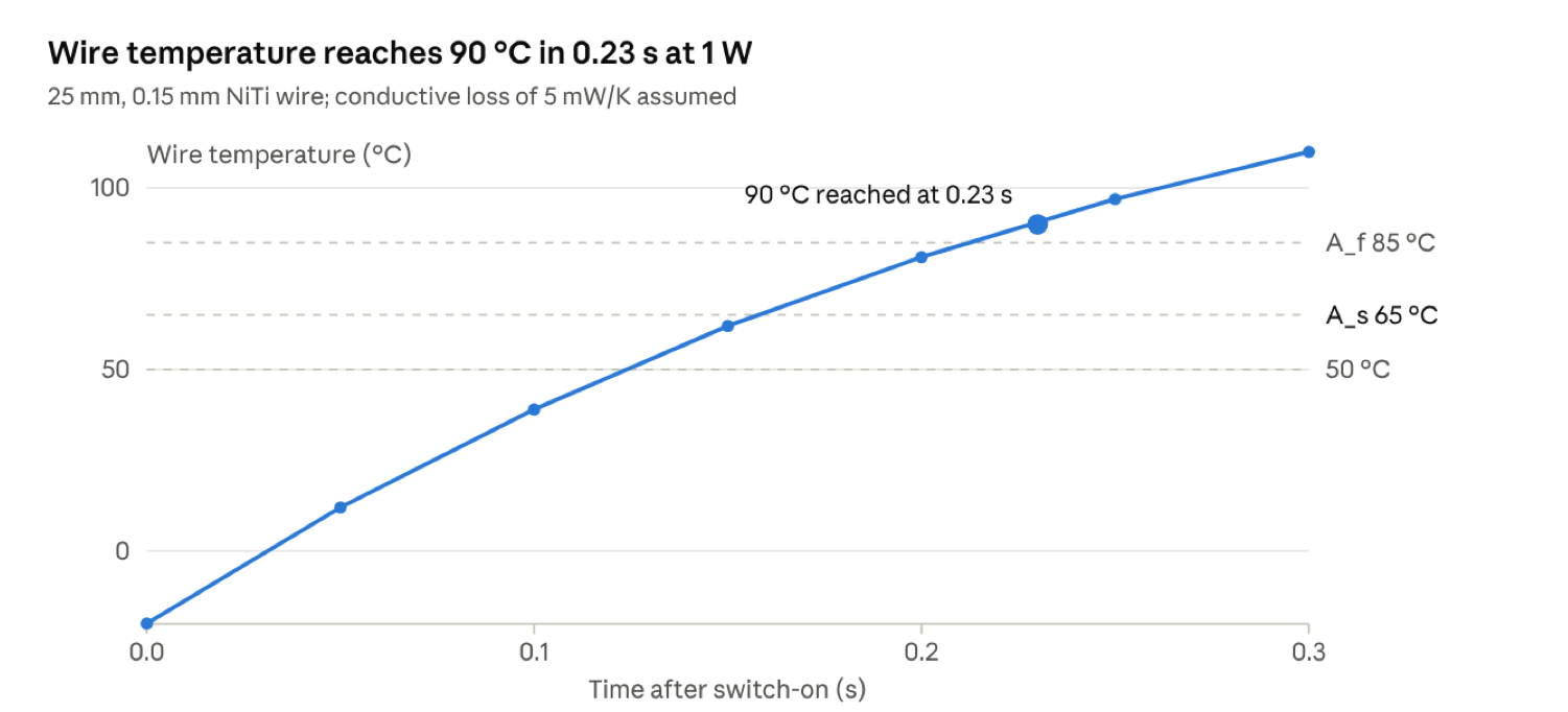
Heating curve of a 25 mm, 0.15 mm one-way NiTi release wire at 1 W. Computed from , with and ; points rounded to .
7.3. Inadvertent actuation#
A stowed wire must not begin to recover in orbit. With , it has a 15 K margin above the 50 °C operating maximum. Recovery begins under load at , so the margin must hold through the whole stowage time at the hottest temperature. This is a dwell test (Section 9). The wire should be thermally decoupled from the electronics and from sunlit surfaces, and its electrical insulation adds outgassing that must be screened (Section 8).
7.4. Ground activation and life#
Each one-way activation uses up the element. Ground activations therefore consume flight hardware, so the flight wire must be a fresh element from the same heat, and all activation tests must use sister wires from that heat. Storage and thermal cycling of the stowed actuator are verification items (Section 9).
8. Restraint filaments, latches and thermal mismatch#
The restraint and the latch must hold for months and then release once. Their failure modes are creep, cold welding and thermal mismatch rather than fatigue, and their outgassing counts against PQ-Gen-04.
8.1. Restraint filaments and burn-wire cutting#
A burn wire is the alternative release path to the SMA latch. It cuts a restraining filament by local melting. The filament carries the hub load of 1.3 to 3.6 N, so a 0.3 mm line carries about 18 to 51 MPa, which is under 2 % of the strength of a typical high-performance fibre [19]. The stress is low, so the choice of filament turns on melting behaviour, creep and moisture, as summarised in Table 7.
Table 7.Candidate restraint filaments for a 0.3 mm line.
| Filament | Melting or cutting | Creep and moisture | Required test |
|---|---|---|---|
| UHMWPE | Melts at about 130 to 136 °C | Low moisture uptake; creep significant under load | Stress relaxation at 50 °C over the stowage time |
| Nylon 6,6 | Melts at about 255 to 265 °C | Moisture uptake raises TML and WVR | Outgassing as received and after bake-out |
| Aramid | Does not melt; needs a hotter cut | Low creep; moisture uptake | Outgassing and cutting reliability |
| Liquid-crystal polymer | High melting point; cut temperature to be measured | Low creep; low moisture uptake | Outgassing and cutting reliability |
For 0.3 mm UHMWPE the cutting energy is about 0.03 J per millimetre, made up of about 0.02 J of sensible heat and 0.015 J of latent heat. A 5 mm contact zone therefore needs about 0.17 J, and energy is again not the limit. Cut time depends on heat transfer into the filament and on the tension it carries, so it must be measured rather than calculated [20]. A resistive burn wire is not a pyrotechnic device in the usual sense, but its classification under PQ-Gen-02 should be confirmed with the launch provider.
8.2. Latches and cold welding#
A latch pin in a bore is the classic cold-welding pair. Like metals adhere most readily in vacuum [8, 9], so the latch should pair dissimilar metals or use a surface with a hard, insulating film. Type III hard anodising is the standard answer for aluminium contacts that touch a deployer (PQ-Mat-03) [1], and the same argument applies to aluminium latch housings. Dry-film lubricants reduce adhesion, but their binders are organic and must pass outgassing, and their life in vacuum must be measured [9]. Every latch pair should be qualified with the impact-and-fretting test of ESA STM-279 [8], because the adhesion it measures is the quantity that Section 4 showed to be decisive.
8.3. Thermal mismatch#
NiTi and aluminium expand at different rates. Austenitic NiTi has an expansion coefficient of about , and martensitic NiTi is lower [12]. The aluminium housing, 6061-T6, expands at [22]. Over a 70 K swing, a 6 mm latch feature moves about 5 µm relative to its aluminium bore. The clearance must exceed this mismatch plus manufacturing tolerance. Otherwise the latch binds in the cold case and rattles in the hot case. Smaller features and compliant mounts reduce the effect, and the latch should be cycled over the full range in vacuum (Section 9).
8.4. Outgassing and contamination#
PQ-Gen-04 limits total mass loss (TML) to 1.0 % and collected volatile condensable material (CVCM) to 0.1 %. The Standard refers to ECSS-Q-ST-70-02C [1, 6], which screens on recovered mass loss, meaning total mass loss minus the water regained (WVR). ASTM E595 screens on total mass loss [7]. The two methods can give different verdicts for hygroscopic materials, so the test method must be declared in the test plan. Nylon and aramid filaments, adhesives and the insulation of the NiTi wire are the most likely to fail on total mass loss while passing on recovered mass loss. The NASA outgassing database gives screening data for many materials [24]. The as-built material, its moisture state and its bake-out condition must be reported for each flight part (Section 9).
9. Verification plan and matrix#
The design rests on five properties that are not yet measured for a flight lot: the transformation temperatures, the plateau stress at three temperatures, the recovery force, the cold-welded adhesion and the outgassing of each non-metal part. Table 8 assigns each to a method and a pass criterion, and names the section that depends on it. The criteria follow from the budgets in Sections 4, 6, 7 and 8. They are design targets, not standard requirements.
Table 8.Verification matrix for the release and deployment element.
| Item | Method | Pass criterion | Section |
|---|---|---|---|
| Transformation temperatures | DSC per ASTM F2004 [16] | Superelastic and ; one-way | 6 |
| Plateau stress and recoverable strain | Tension per ASTM F2516 [17] at −20, 25 and 50 °C | Plateau at 50 °C below the austenite slip threshold; recoverable strain ≥ 4 % | 3, 6.2 |
| Coiling set | Coil on a 3 mm hub for 10 cycles | No set beyond the latch clearance | 3 |
| Release force | Load cell in thermal chamber | ≥ 2 × hot-case restraint, i.e. ≥ 7.2 N with two wires | 7.1 |
| Release time and energy | Current and time logging at 1 W, at −20 and +50 °C | Release within 1 s; energy ≤ 0.5 J | 7.2 |
| Dwell and inadvertent actuation | 50 °C dwell in vacuum for the stowage time, then DSC | No measurable recovery; margin ≥ 10 K | 7.3 |
| Cold-welded adhesion | ESA STM-279 test [8], after vibration and dwell | ≤ 0.35 N over the stroke at −20 °C | 4.2, 8.2 |
| Filament creep | Tension–time test at 50 °C [19] | Tension stays above the hub load for the stowage time | 8.1 |
| Outgassing | ECSS-Q-ST-70-02C [6]; ASTM E595 [7] | TML ≤ 1.0 %, CVCM ≤ 0.1 % | 8.4 |
| Latch cycling | Thermal-vacuum cycles from −20 to +50 °C | Release without binding or rattle | 8.3 |
The test sequence follows the order in which the risks appear. Every destructive test uses a sister element from the same heat.
- Measure the transformation temperatures of each melt by differential scanning calorimetry, and reject lots outside the windows in Table 5.
- Measure the superelastic plateau at −20, 25 and 50 °C in tension, and confirm that the plateau at 50 °C stays below the austenite slip threshold.
- Coil flight-representative tape on a 3 mm hub for ten cycles, and record set and recoverable strain.
- Measure the recovery force of the one-way wire at 50 °C, and confirm a margin of at least two for the two-wire configuration.
- Measure the outgassing of every non-metal part by ASTM E595 and by ECSS-Q-ST-70-02C.
- Run the cold-welding test on each latch pair after vibration and vacuum dwell, using ESA STM-279 [8].
- Cycle the thermal-vacuum chamber from −20 to +50 °C, and hold the stowed element at 50 °C for the full stowage time.
- Release the element at −20 and +50 °C, logging time, current and force, and check that the latch does not bind.
- Repeat the sequence on a flight-representative 1P unit with launch-level vibration, as the launch service provider specifies [1].
Two results would change the design. First, if the austenite slips at the 50 °C plateau, the remedy lies in the alloy or in the thermal design, not in the geometry, because the plateau stress is a material property set by the slope and the finish temperature. Second, a cold-welded adhesion above 0.35 N would consume 30 % of the cold-case energy, and the latch pair or the guide would then have to be changed before the NiTi option could be kept.
10. Discussion#
10.1. Architecture trade-off#
Four architectures fit the 7 mm component envelope with a 6 mm stack. Spring steel at 0.036 mm is the simplest to qualify, since it uses one composition and needs no transformation tests. It stores about one-fifth of the NiTi energy at −20 °C and absorbs its entire energy under only 0.24 N of adhesion. A CFRP tape spring at 0.06 mm satisfies the strain budget, but its matrix adds an organic phase that must pass outgassing [6, 7]. Superelastic NiTi with a one-way NiTi latch, as recommended in this article, needs two compositions and a transformation qualification, but it keeps the stored energy and the adhesion tolerance. A burn-wire backup on the same hub adds an independent release path. It is attractive if the launch service provider accepts a resistive burn wire under PQ-Gen-02.
10.2. Longer elements#
The reference element is a quarter-wave UHF element. Larger missions need longer elements. The 5 m dipole of the Delfi-Twin RABSII payload is built from two 2.5 m elements [4], so the same analysis applies at 2.5 m, with the coil model of Section 2 extended to 64 wraps for NiTi and 87 for spring steel. Table 9 compares the two lengths.
Table 9.Coil estimates for the 170 mm reference element and a 2.5 m element on a 3 mm hub. Stored energy and adhesion are for −20 °C.
| Quantity | NiTi, 170 mm | NiTi, 2.5 m | Spring steel, 2.5 m |
|---|---|---|---|
| Wraps | 8 | 64 | 87 |
| Coil outer diameter | 7.6 mm | 18.8 mm | 12.3 mm |
| Element mass | 0.7 g | 9.7 g | 4.3 g |
| Stored energy | 0.20 J | 1.6 J | 0.28 J |
| Adhesion that absorbs all stored energy | 1.15 N | 0.63 N | 0.11 N |
The energy per unit length falls as the coil grows, because each wrap sits on a larger radius and carries less curvature. Adhesion tolerance falls with it. NiTi keeps a five- to sixfold energy advantage at both lengths. However, a 2.5 m NiTi element tolerates only 0.63 N of adhesion at −20 °C, which is a demanding requirement for a latch and a guide. A dipole has two such elements, so the mass and stored energy in Table 9 double, and each element needs its own latch.
10.3. Limitations#
The models are first order, and their limits bear on the decisions above. The superelastic moment is an upper estimate, because the inner layers remain elastic. The plateau stress rests on an assumed zero-stress martensite start and on a Clausius–Clapeyron slope taken from the literature [10, 11], so a measured plateau curve is needed. The coil model neglects friction between wraps and the interaction of neighbouring wraps. The recovery stress, the electrical resistivity, the latent heat and the conductive loss are assumed. Fatigue and creep of NiTi and of the restraint filaments are not modelled, and neither is the cycling of the coil. The radio-frequency cost of NiTi is also outside the scope. Its resistivity is roughly fifty times that of copper, which is why TU Delft investigated conductive coatings for the Delfi-Twin antennas [5]. Any coating must survive the 1.7 % outer-fibre strain of the reference coil without cracking, and the coating study tested its wires in bending [5].
10.4. Relation to the Delfi-Twin programme#
The Delfi-Twin programme is the most direct test of this analysis. Its nitinol antennas [5] are one of the options compared here. Its hinge-and-torsion-spring design [4] represents a third family that avoids strain-limited tapes, because the spring is sized as a coil rather than folded as a tape. The analysis above supports the nitinol choice at the 1P hub, provided that the transformation window, the 50 °C plateau and the cold-welding margin are measured on the flight lot. The article therefore supplies the mechanical side of the trade, and the coating study supplies the electrical side.
11. Conclusions#
- For a 1P antenna element, the strain budget rather than the actuator energy sets the feasible tape thickness. A 0.10 mm tape on a 3 mm hub reaches an outer-fibre strain of 1.67 %, which only superelastic NiTi tolerates with margin.
- Spring steel must thin to 0.036 mm to stay elastic on that hub. Its stored energy at −20 °C is about one-fifth of the NiTi value, and it absorbs its entire energy under only 0.24 N of adhesion.
- Cold welding is the decisive deployment risk. A 1 N adhesion over the 170 mm stroke absorbs about 87 % of the NiTi energy at −20 °C, so deployment must be verified at the cold end, and every latch pair must be qualified in vacuum.
- Under a constant strain budget, halving the cube edge halves the admissible thickness, the stored energy per unit length, the restraint force and the energy margin. The 1U answer of spring steel therefore does not carry over to 1P.
- The superelastic plateau rises by about 6.5 MPa per kelvin, to about 715 MPa at 50 °C. Showing that the austenite tolerates this stress without slip is the most important materials test of the superelastic option.
- A one-way NiTi wire of 0.15 mm diameter supplies about 5 N, reaches 90 °C in 0.23 s at 1 W and needs about 0.23 J. Its start temperature of 65 °C leaves a 15 K margin above the 50 °C operating maximum. Two wires in parallel provide the hot-end force margin that the latch requires.
- The design is consistent with the PocketQube Standard, which excludes pyrotechnic devices, limits components to a 7 mm envelope and requires deployables to be retained by the spacecraft. The materials require launch-provider consultation under PQ-Mat-04, and the outgassing of every non-metal part must meet TML ≤ 1.0 % and CVCM ≤ 0.1 %.
The two priority experiments are the plateau measurement at 50 °C and the cold-welding test on the latch pair. The models here are first order, and their parameters should be replaced by measured values as soon as they are available.
Declarations#
Competing interest. nadir lab. declares no known competing financial interests or personal relationships that could have appeared to influence the work reported in this paper.
Data availability. The calculations behind Tables 3, 4, 6 and 9 and Figures 1 and 2 can be reproduced from the inputs in Appendix A.
Use of generative AI. During the preparation of this monograph for exclusive publication on nadir lab., generative AI tools (Claude, Anthropic) were used to assist with literature synthesis, first-order analytical model verification, language editing and figure preparation. After using these tools, the nadir lab. research group reviewed, verified and edited the content and calculations as needed and takes full responsibility for the content of the publication.
Appendix A. Model inputs#
Table A.1.Inputs of the first-order models in Sections 2 to 9. Values marked as assumed or to be measured must be replaced before design.
| Input | Value used | Source or status |
|---|---|---|
| Cube edge, 1P and 1U | 50 mm and 100 mm | Standard dimensions [1] |
| 1P mass limit | 250 g | PQ-Mass-01 [1] |
| Component envelope and deployable allowance | 7 mm; 10 mm with waiver | PQ-Mech-08 [1] |
| Outgassing limits | TML ≤ 1.0 %; CVCM ≤ 0.1 % | PQ-Gen-04 [1]; [6, 7] |
| Tape width | 6 mm | Design choice, sized to the 7 mm envelope |
| Element length | 170 mm (UHF quarter-wave); 2.5 m (dipole element) | Band lengths; 2.5 m from [4] |
| Hub radius | 3 mm baseline; 4 mm and 5 mm sensitivity | Design choice |
| Operating range | −20 °C to +50 °C | Design assumption |
| Spring steel | ; | Representative values [21, 22] |
| 17-7PH, TH1050 | ; ; | Representative values [22] |
| Ti-6Al-4V, annealed | ; ; | Representative values [22] |
| Beryllium copper, heat-treated | ; | Representative values [22]; benchmark only |
| Unidirectional CFRP tape spring | Assumption | |
| Superelastic NiTi, aged | design value; plateau strain 6 to 8 % in good material | Literature [10, 15]; to be measured |
| NiTi austenite modulus | 60 to 80 GPa | Literature [10, 12]; to be measured |
| NiTi density | Literature [12] | |
| NiTi specific heat | Assumed | |
| NiTi resistivity, austenite | Assumed from literature [12]; to be measured | |
| Clausius–Clapeyron slope | Literature [10, 11, 13] | |
| Zero-stress martensite start | −60 °C | Assumed for a Ni-rich aged alloy; to be measured by DSC [16] and tension [17] |
| Plateau stress | 260, 550 and 715 MPa at −20, 25 and 50 °C | ; upper estimate for the moment |
| NiTi latent heat | Assumed lower bound; to be measured [16] | |
| One-way recovery stress | 300 MPa | Assumed; to be measured |
| One-way transformation temperatures | ; | Design targets (Section 6) |
| Conductive loss through clamps, | Assumed; to be measured | |
| UHMWPE filament | ; ; ; | Representative values [19] |
| Heat-transfer method | Lumped capacitance with a single conductance | [20] |
| Materials list | Aluminium alloys of PQ-Mat-02, referenced to ECSS-Q-ST-70-36C | [1, 23] |